
Protective barrier

Inactive Publication Date: 2004-01-08
VAN HALE GREGORY
View PDF4 Cites 9 Cited by
  • Summary
  • Abstract
  • Description
  • Claims
  • Application Information

AI Technical Summary

Benefits of technology

[0015] Another object of the invention is to provide a protective barrier of the character described in the preceding paragraphs that is lightweight, durable and easy-to-use and one that permits positive gripping and control of the dental instrument during use.
[0016] Another object of the invention is to provide a protective barrier that can be inexpensively fabricated in quantity using well-known plastic molding techniques.

Problems solved by technology

A common drawback of the prior art barrier devices resides in the fact that the dental instrument is more difficult to grip and to manipulate after the barrier device has been interconnected with the dental instrument.
Another drawback of the prior art barrier devices concerns the difficulty in initially attaching the barrier device securely to the dental instrument and then the removal of the barrier device from the dental instrument following completion of the dental procedure.

Method used


Image

  • Protective barrier
  • Protective barrier
  • Protective barrier

Examples


Embodiment Construction

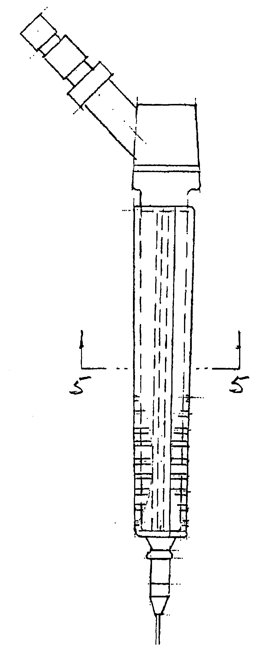
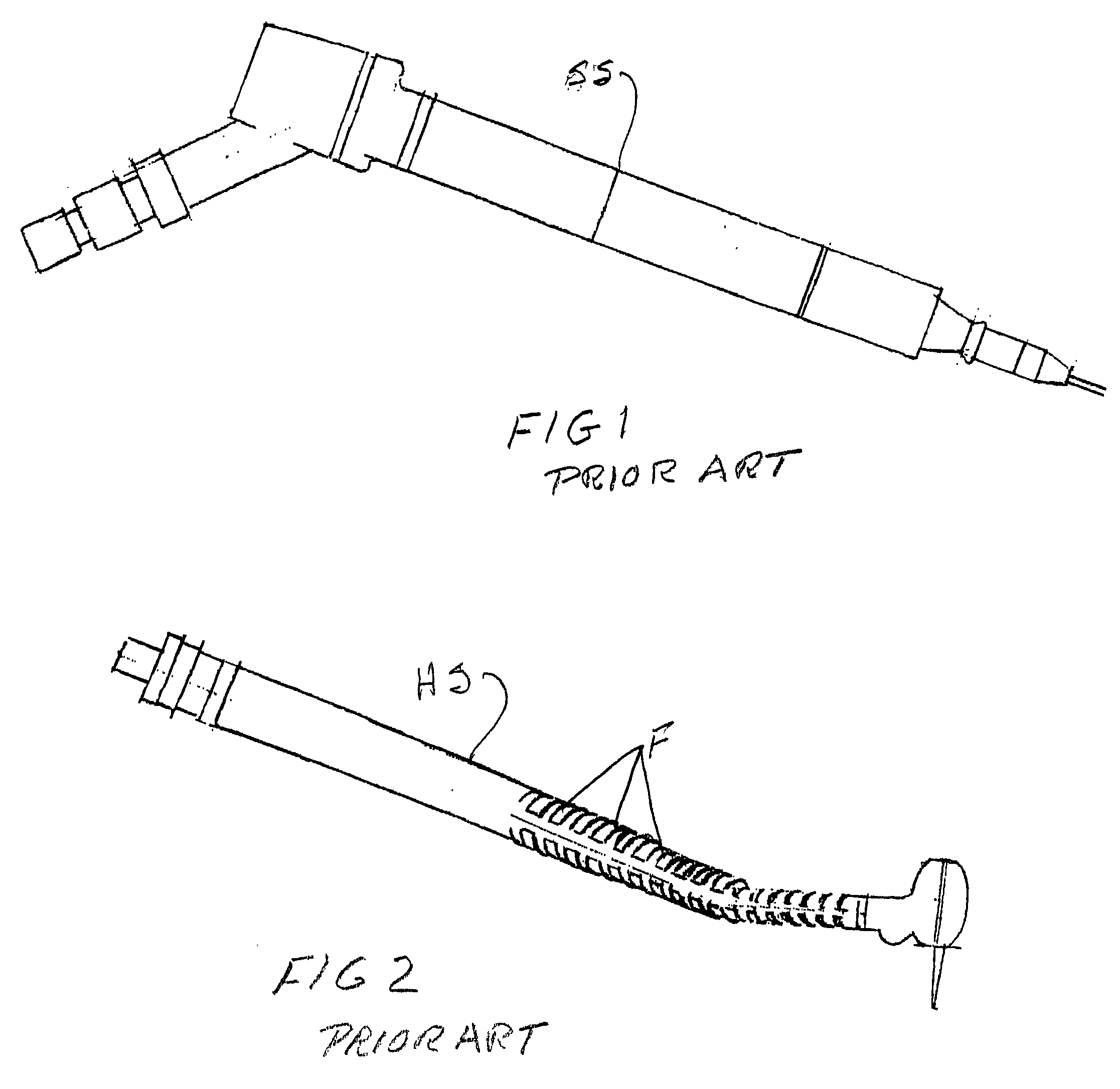
[0033] Referring to the drawings and particularly to FIGS. 1 and 2, two types of prior art dental instruments of the type with which the protective barrier devices of the present invention can be used are there shown. In FIG. 1 a slow speed dental hand piece "SS" is illustrated and in FIG. 2 a high-speed dental hand piece "HS" is shown. It is be understood that these hand pieces are merely exemplary of the many different types of dental instruments with which the barrier devices of the present invention can be used. For example, the protective barriers of the invention can be specially constructed for use with aspirating units of various designs, dental drills of various designs, scalars, saliva ejector instruments and air / water supply instruments.

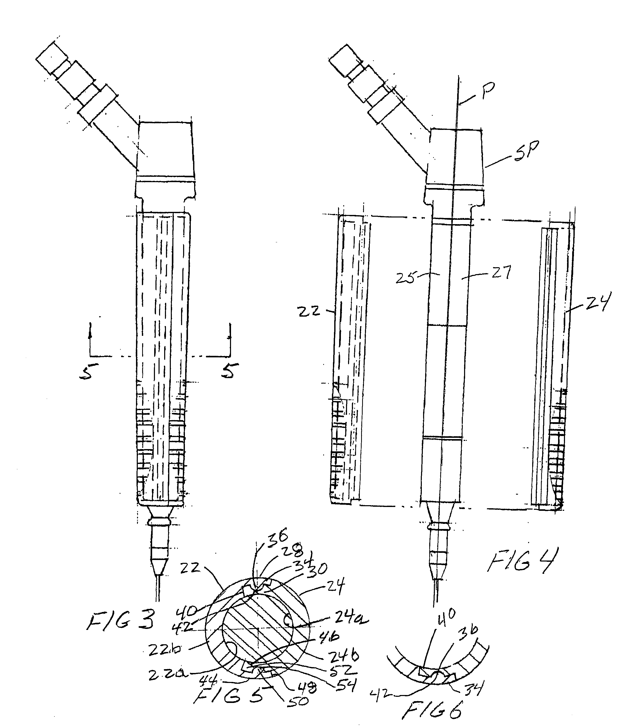
[0034] Turning to FIGS. 3 through 6, one form of protective barrier device of the invention is there shown for use in connection with a slow speed dental instrument SS of the character shown in FIG. 1. This protective barrier is designed f...


PUM


Abstract

A protective barrier that can be removably fitted over a dental instrument to protect against the transfer of contaminants from one dental patient to another via the dental instrument. The protective barrier, which generally replicates the ergonomic features found on the outer surface of the dental instrument, is constructed from two mating segments that are adapted for placement over and in proximate contact with at least a portion of the outer surface of a dental instrument.

Description

[0001] 1. Field of the Invention[0002] The present invention relates to protective barriers. More particularly, the invention relates to protective barriers for use with dental instruments to prevent the spread the contaminants.[0003] It has long been recognized in the dental industry that after an infectious agent from one patient contaminates a dental instrument, the instrument has the potential to spread the contaminants to the next patient unless special care is taken to replace the instrument or properly sterilize it. As a general rule, replacing the instrument parts which are vulnerable to contamination is prohibitively expensive and sterilizing the parts by autoclaving is time consuming. While attempts have been made in the past to sterilize the instrument parts by spraying the parts with a disinfectant, experience has shown that such an approach is inadequate to effectively remove all contaminants.[0004] In the past, various attempts have been made to provide protective plas...

Claims


Application Information

Patent Timeline
IPC IPC(8): A61C1/16
CPCA61C1/16
Inventor VAN HALE, GREGORY
Owner VAN HALE GREGORY
Learn More