
Magnetized hand tools

a technology of hand tools and magnets, applied in the field of hand tools, can solve the problems of not being able to solve the problem in a complete way, the material does nothing to retain the tool(s) positively, and the relative softness of the padded material is often subject to deterioration, so as to enhance the grip of the user the positive grip of the padded material

Inactive Publication Date: 2011-12-22
ALFARO NELSON B
View PDF6 Cites 6 Cited by
  • Summary
  • Abstract
  • Description
  • Claims
  • Application Information

AI Technical Summary

Benefits of technology

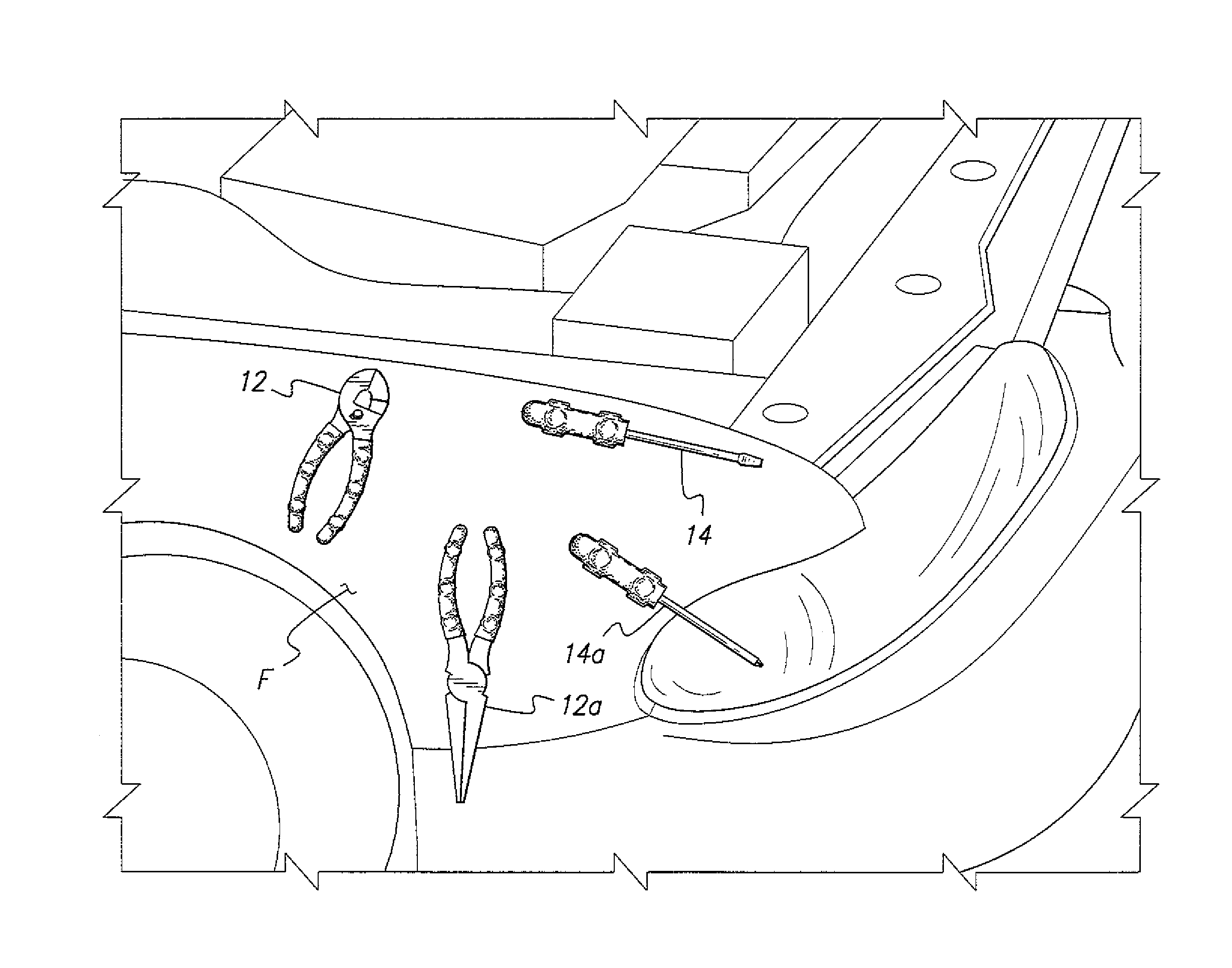
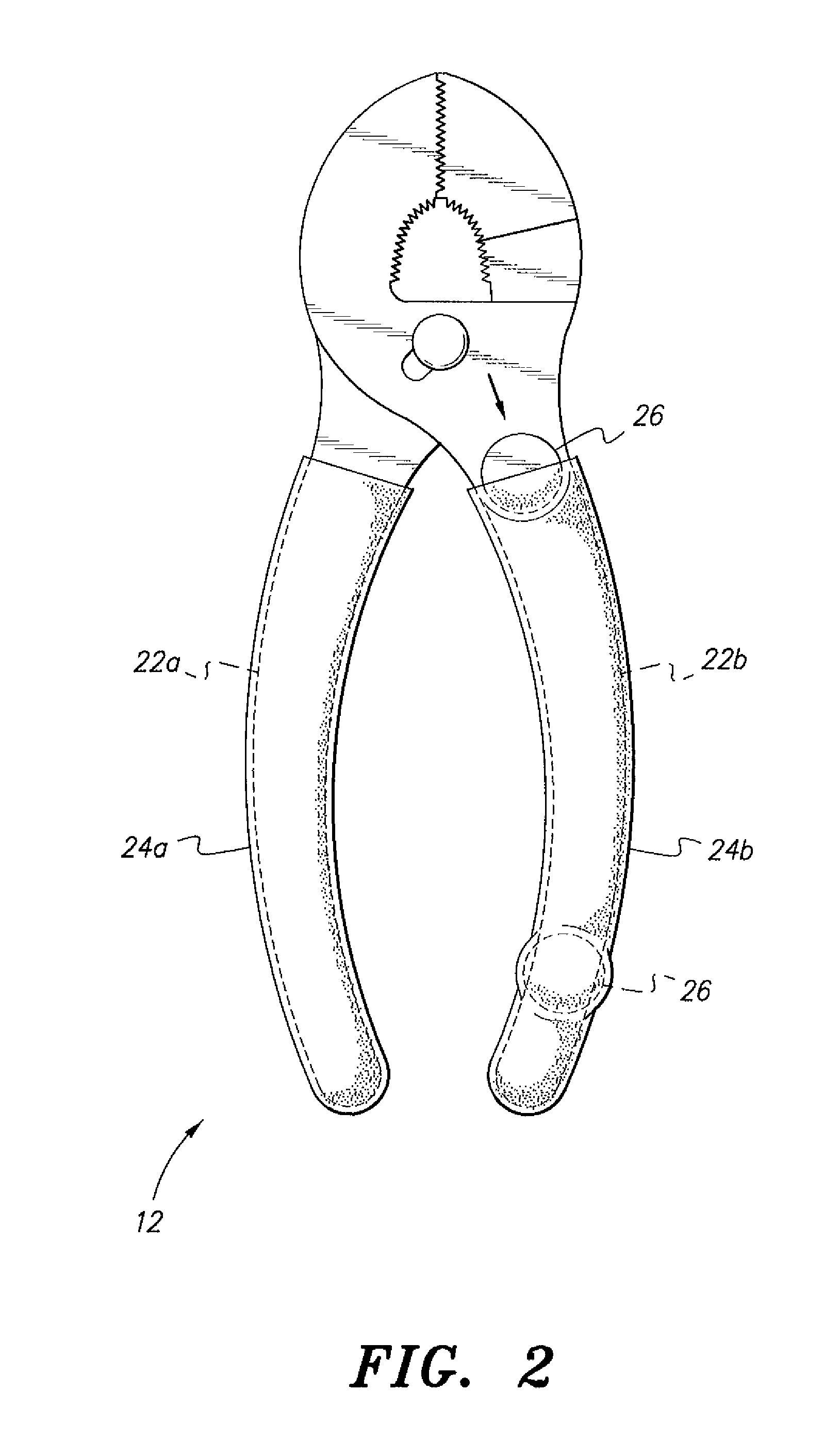
[0011]The magnets may be adhesively or otherwise positively secured to the tools, in addition to being retained thereon by the resilient sleeves. The tools may include one or more recesses for the magnets so that the magnets nest in the recesses for additional positive retention. The magnets preferably protrude from the surfaces of the tool handles sufficiently to form a series of protuberances in the surfaces of the overlying sleeves, thereby providing uneven surfaces to enhance the grip of the user of the tool. In the case of sockets, the magnets are preferably embedded in the bases of the sockets with little or no protrusion therefrom, enabling the overlying sleeves to lie immediately adjacent to the surfaces of the socket bases. A method of magnetizing hand tools by means of the above-described structure is also provided.

Problems solved by technology

One solution to this problem has been the placement of a padded sheet of material in the bottom of the tool chest drawer, but such relatively soft padded material is often subject to deterioration due to the impact of tools as they are replaced in the drawer, and such material does nothing to retain the tool(s) positively in a specific position in the drawer.
Oftentimes the owners of the tools will mark their desired storage locations on the board, and while this can help to keep the tools organized, it is not a complete answer to the problem.
The hooks, hangers, and other fasteners hanging from the pegboard are prone to being dislodged from their attachment holes, and the tools themselves often do not hang or reside neatly in their assigned positions due to their being primarily configured for use rather than storage, as noted further above.

Method used


Image

  • Magnetized hand tools
  • Magnetized hand tools
  • Magnetized hand tools

Examples


Embodiment Construction

[0019]The magnetized hand tools described herein do not necessarily include magnetized working ends to attract ferrous metal parts (screws, etc.) thereto, but may include such magnetism in their working ends or parts, if so desired. Rather, the magnetized hand tools include magnets installed to their handles or bases to facilitate attachment of the tools to a ferrous metal panel or the like for storage, or to a ferromagnetic workpiece.

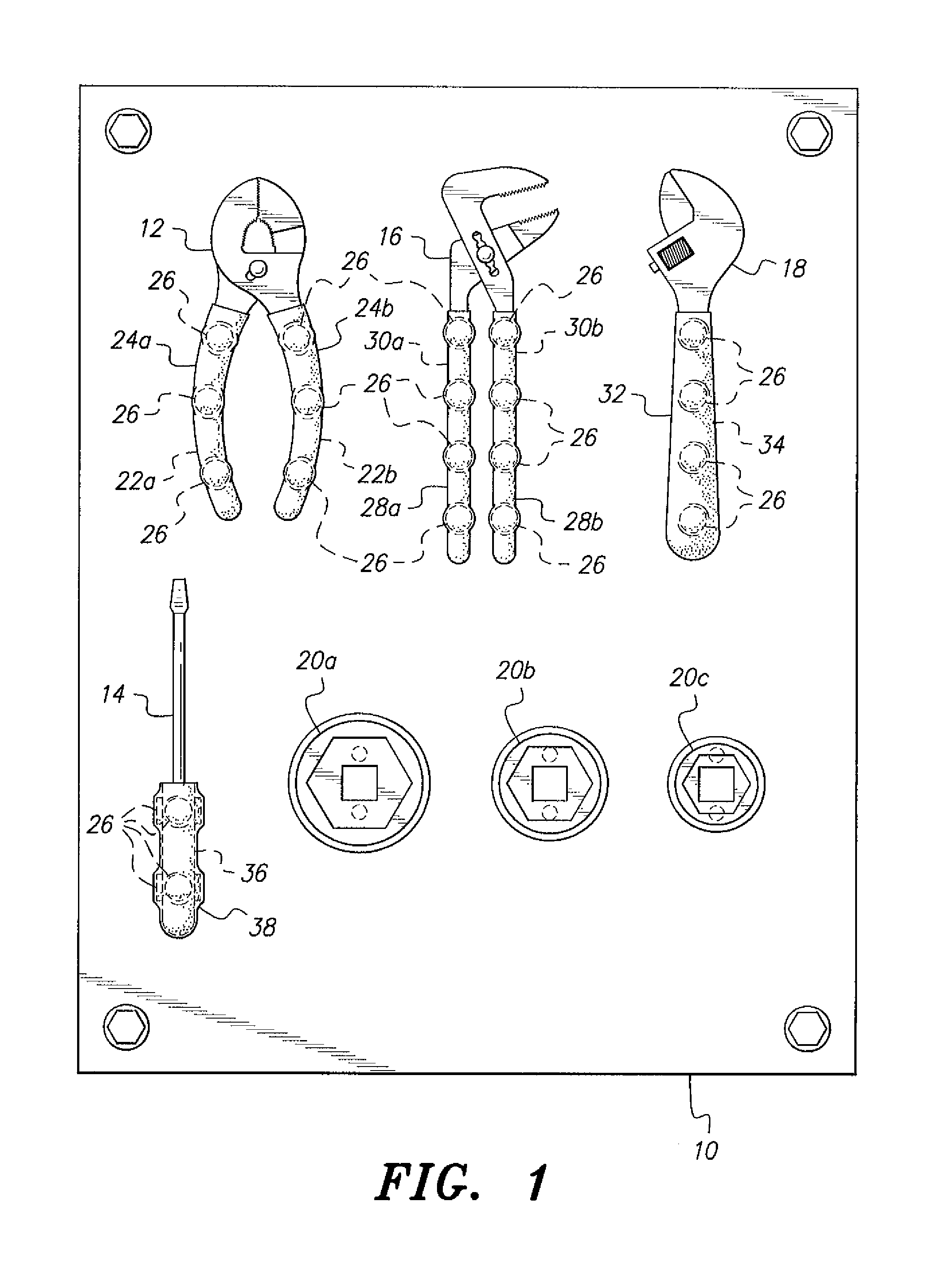
[0020]FIG. 1 of the drawings is an illustration of such an arrangement. A ferrous metal tool storage plate 10 is secured to an underlying structure (e.g., garage or shop wall, etc., not shown), and serves as a storage panel or location for the tools of the present invention. It will be seen that the panel or plate 10 need not be a flat sheet of metal, but may be of any practicable configuration or shape so long as it is capable of magnetically retaining another magnetically attractive object(s).

[0021]The tool storage plate 10 of FIG. 1 is shown with a ...


PUM

PropertyMeasurementUnit
magnetic retentionaaaaaaaaaa
resilientaaaaaaaaaa
timeaaaaaaaaaa

Abstract

The magnetized hand tools each include a sleeve of resilient material disposed over each handle or the base of the tool. One or more magnets are installed between the tool handle(s) and the resilient grip(s) covering the handle(s). Alternatively, the tool may have one or more magnets installed in the base, i.e., the drive attachment end, of a socket, with a sleeve being applied over the base of the socket to retain the magnet(s). The socket sleeve has a passage therethrough for the conventional square drive of the ratchet or other tool used to drive the socket. The magnets are recessed into the base of the socket to allow the overlying sleeve portion to lie immediately adjacent to the surface of the socket base, and may be inset into recesses in the tool handles and / or positively attached thereto for more positive retention.

Description

CROSS-REFERENCE TO RELATED APPLICATION[0001]This application claims the benefit of U.S. Provisional Patent Application Ser. No. 61 / 344,270, filed Jun. 21, 2010.BACKGROUND OF THE INVENTION[0002]1. Field of the Invention[0003]The present invention relates generally to hand tools, and particularly to magnetized hand tools having magnetized handles, bases, or other portions, enabling those tools to be secured removably to a ferrous metal panel for storage or to a ferromagnetic workpiece.[0004]2. Description of the Related Art[0005]Tools in general are configured primarily for their use, with little or no consideration being given to their storage when not in use. Hand tools are often tossed into a tool chest drawer or the like for storage, where they are subject to sliding around and being mixed with other tools each time the drawer is opened or closed and / or the chest is moved. One solution to this problem has been the placement of a padded sheet of material in the bottom of the tool c...

Claims


Application Information

Patent Timeline
Patent Type & Authority Applications(United States)
IPC IPC(8): B25H3/00B25G1/10B23P11/00B25B23/16
CPCY10T29/49826B25G1/10
Inventor ALFARO, NELSON B.
Owner ALFARO NELSON B
Learn More