
Belt-driven coin separating apparatus

Active Publication Date: 2005-02-24
ASAHI SEIKO CO LTD
View PDF18 Cites 5 Cited by
  • Summary
  • Abstract
  • Description
  • Claims
  • Application Information

AI Technical Summary

Benefits of technology

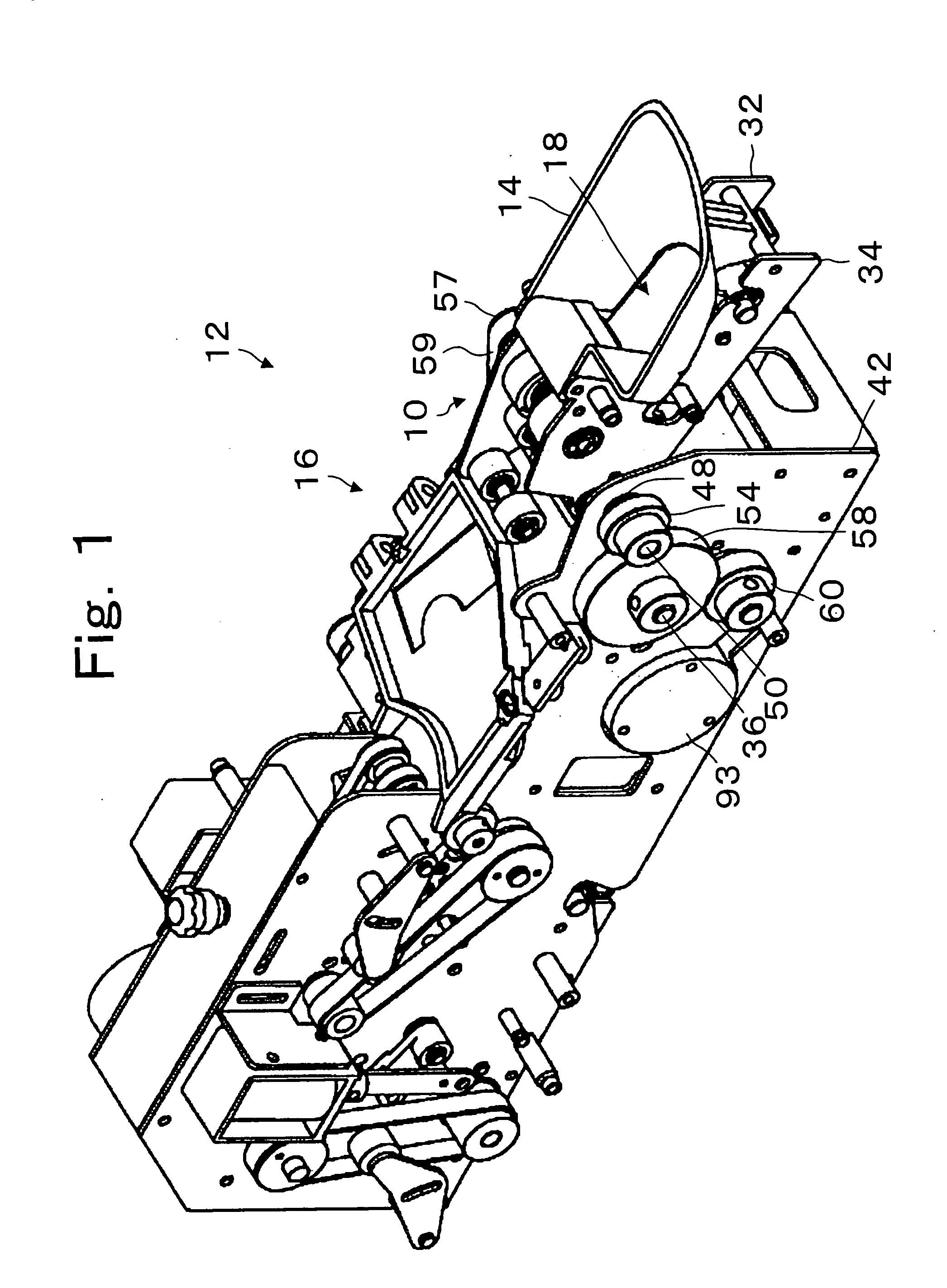
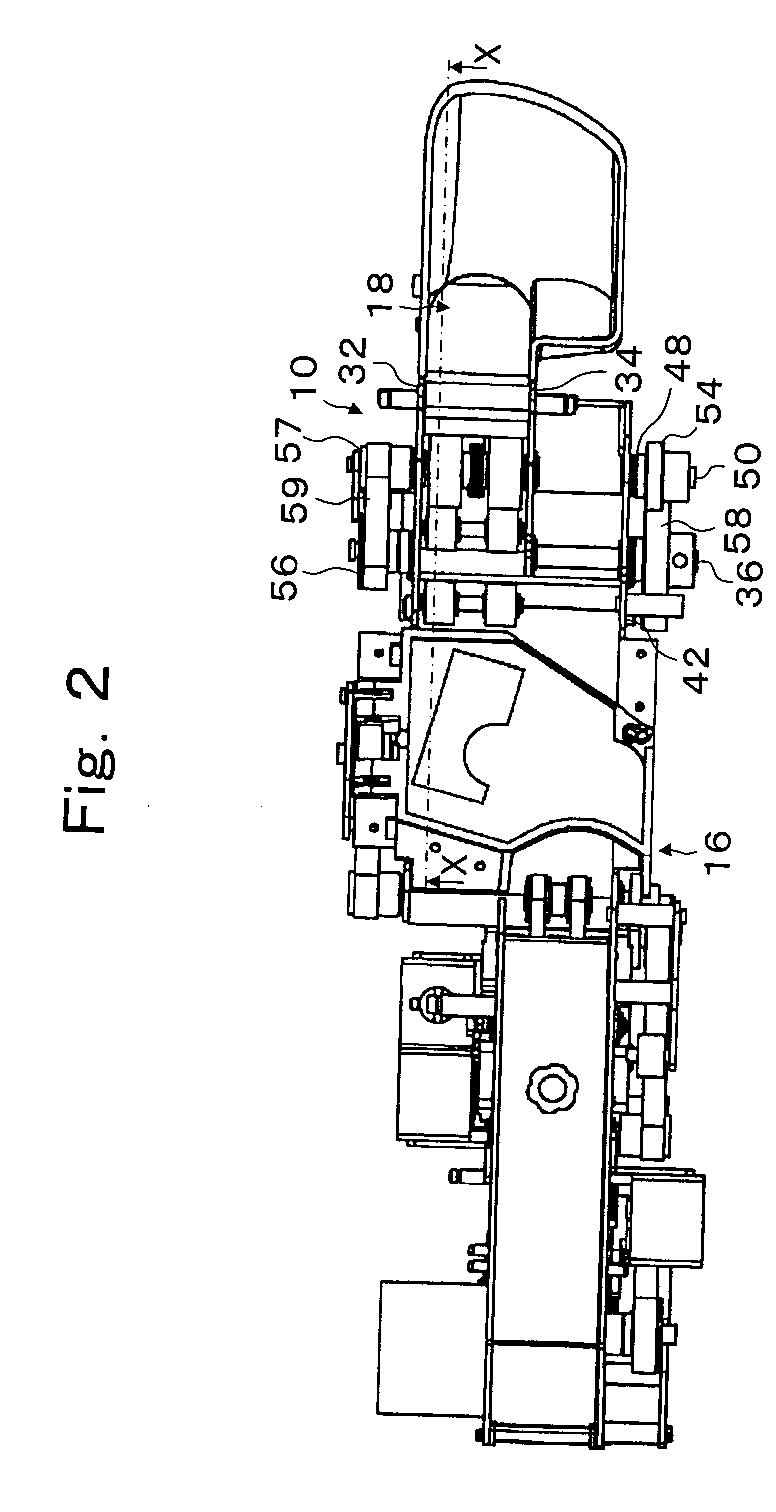
[0006] The present invention provides a relatively inexpensive and compact coin separating unit which can separate coins stored in bulk which are released onto a lower transporting belt while preventing jamming effects despite the varying thicknesses of the coins. The coin separating unit can separate the bulk coins one by one despite various thickness differences between different types of coins.
[0007] The present invention provides a coin separating unit of a relatively inexpensive configuration which includes a coin transporting unit that can operatively interact with a hopper or bulk coin dispenser. The coin transporting unit receives the coins and transports them for subsequent processing. A separating roller unit can be provided above the coin transporting unit and set, for example, to provide a gap space of approximately two times the thinnest of the coins that it will process. The roller's surface can move in an opposite or counter-direction to the coin supporting surface of the transporting belt. The belt and the separating roller, however, are also designed to move relative to each other for increasing the gap space under certain circumstances. A supporting unit such as a roller can be located upstream from the separating roller and is also spaced above the coin supporting surface of the belt at a distance which is approximately the thickness of the thinnest coins to be processed. The supporting roller can move relative to the coin transporting unit when contacted by a coin on the belt.

Problems solved by technology

The prior art has experienced problems with smaller sized coins that could pass through such a space, and attempts have been made to narrow the gap between the belt and the roller.
However, this solution sometimes has difficulty if thicker coins are utilized.

Method used


Image

  • Belt-driven coin separating apparatus
  • Belt-driven coin separating apparatus
  • Belt-driven coin separating apparatus

Examples


Embodiment Construction

[0032] Reference will now be made in detail to the preferred embodiments of the invention which set forth the best modes contemplated to carry out the invention, examples of which are illustrated in the accompanying drawings. While the invention will be described in conjunction with the preferred embodiments, it will be understood that they are not intended to limit the invention to these embodiments. On the contrary, the invention is intended to cover alternatives, modifications and equivalents, which may be included within the spirit and scope of the invention as defined by the appended claims. Furthermore, in the following detailed description of the present invention, numerous specific details are set forth in order to provide a thorough understanding of the present invention. However, it will be obvious to one of ordinary skill in the art that the present invention may be practiced without these specific details. In other instances, well known methods, procedures, components, a...


PUM


Abstract

A coin separating unit of a compact configuration for separating coins of different thicknesses from a bulk supply includes a coin transporting unit such as a rotating belt having a support surface of a predetermined flexibility and friction characteristic. A separating roller unit is positioned above a support surface and rotates in a direction opposite to the movement of the belt. A supporter unit is operatively located upstream of the separating roller unit and can displace coins that are overlaid with each other. The belt has sufficient flexibility so that a gap between the surface of the belt and a separating roller unit can be increased to accommodate a particular thickness of coin as it passes beneath the separating roller unit.

Description

BACKGROUND OF THE INVENTION [0001] 1. Field of the Invention [0002] The present invention is directed to the separation of coins fed in bulk and more particularly to a relatively efficient and inexpensive separation of relatively small amounts of coins of different sizes presented in a bulk condition for transportation by a belt. [0003] 2. Description of Related Art [0004] There are various examples in the industry of distributing coins, medallions, tokens, and various forms of monetary coins of separating such items. For example, Japanese Laid-open Patent Application 2002-99939 teaches a transporting belt that can transport bulk coins on the belt to a roller positioned at a distance which is slightly greater than the thickness of the bigger coins to be separated and slightly thinner than two relatively thin coins that can be overlaid. The roller can rotate in an opposite direction or a counter direction to the transporting direction of the belt. If coins become stuck between the tr...

Claims


Application Information

Patent Timeline
IPC IPC(8): G07D1/00A63F5/04G07D9/00G07F1/02
CPCG07D9/008
Inventor UMEDA, MASAYOSHI
Owner ASAHI SEIKO CO LTD
Learn More