
Optical fiber grating, optical fiber grating manufacturing method, and optical fiber grating manufacturing apparatus

a technology of optical fiber grating and manufacturing method, which is applied in the direction of cladded optical fibre, instruments, optical elements, etc., can solve the problems of difficult to guarantee a high yield and maintain the stability of optical properties in this environment over the long term, and achieve precise control of optical properties, modulation or fluctuation of optical propertying, and the effect of extending the optical fiber

Inactive Publication Date: 2005-02-24
ISHII YUU +4
View PDF8 Cites 6 Cited by
  • Summary
  • Abstract
  • Description
  • Claims
  • Application Information

AI Technical Summary

Benefits of technology

[0023] In order to resolve the above-described problems, in the present invention, the following resolution device is proposed. According to the optical fiber grating manufacturing method of the present invention, the uniform ultraviolet irradiation processing and the heat processing are carried out in a suitable combination, and thereby, the central wavelength of the optical fiber grating and the rejection ratio at the central wavelength can be adjusted, and an optical fiber grating having the target optical properties can be obtained.
[0024] A first aspect of the present invention is a manufacturing method for an optical fiber grating comprising the steps of: forming a grating part having a periodic refractive index distribution by irradiating an optical fiber along the longitudinal direction by ultraviolet light at a predetermined period and carrying out dehydrogenation when necessary; carrying out at least one time uniform ultraviolet irradiation processing that irradiates the grating part as a whole with ultraviolet light; and carrying out heat aging in order to stabilize the optical properties of the grating part.
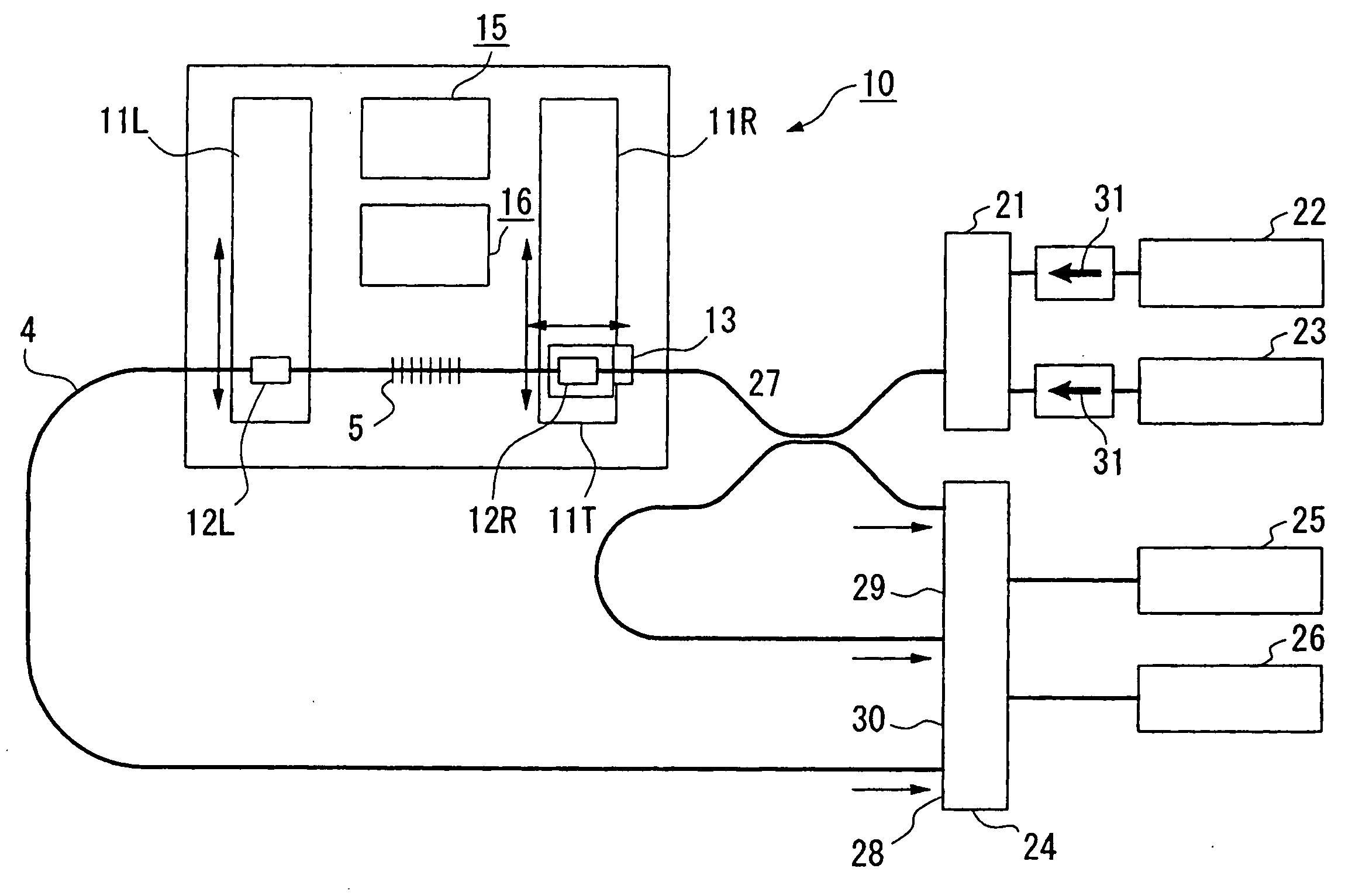
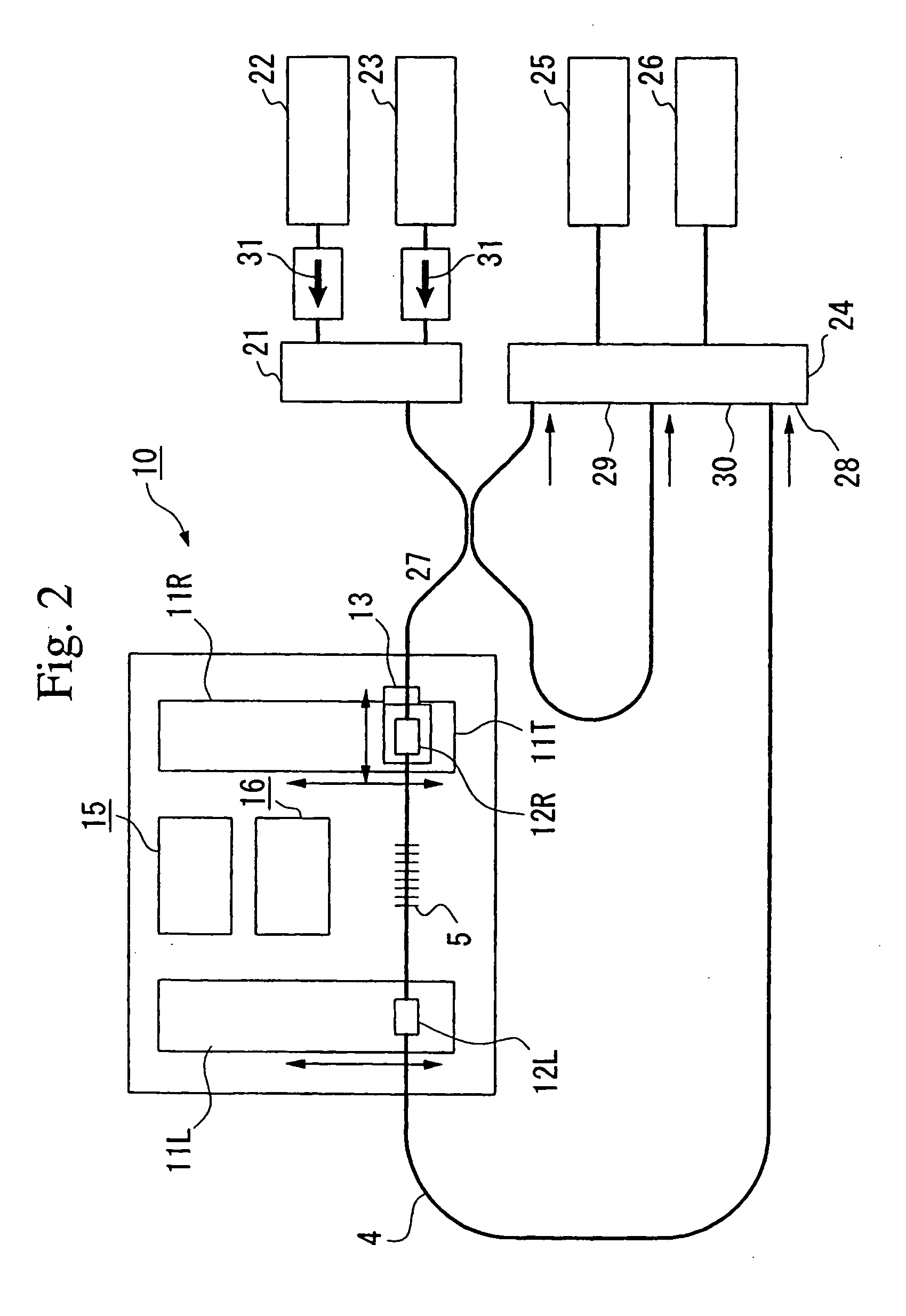
[0032] According to the optical fiber grating apparatus of the present invention, the optical properties of the optical fiber grating are measured, and depending on the results of this measurement, suitable ultraviolet irradiation processing and heat processing can be easily carried out. In addition, the tension of the optical fiber can be maintained at a suitable constant by a tension maintaining mechanism provided on the fiber clamp, and thereby modulation or fluctuation of the optical propertied due to insufficient or excess tension or changes in the tension can be prevented, and precise control of the optical properties becomes possible.

Problems solved by technology

Therefore, if only the central wavelength is of concern, it can be controlled comparatively stably, but there is no adjustment mechanism for the rejection ratio, and while the optical properties of the product can be stably maintained, there is difficulty in guaranteeing a high yield.
In addition, the change of the refractive index of the optical fiber grating is sensitive to the heat environment (that is, thermal instability) particularly after ultraviolet irradiation, and stably maintaining the stability of the optical properties in this environment over the long term is difficult.

Method used


Image

  • Optical fiber grating, optical fiber grating manufacturing method, and optical fiber grating manufacturing apparatus
  • Optical fiber grating, optical fiber grating manufacturing method, and optical fiber grating manufacturing apparatus
  • Optical fiber grating, optical fiber grating manufacturing method, and optical fiber grating manufacturing apparatus

Examples


Embodiment Construction

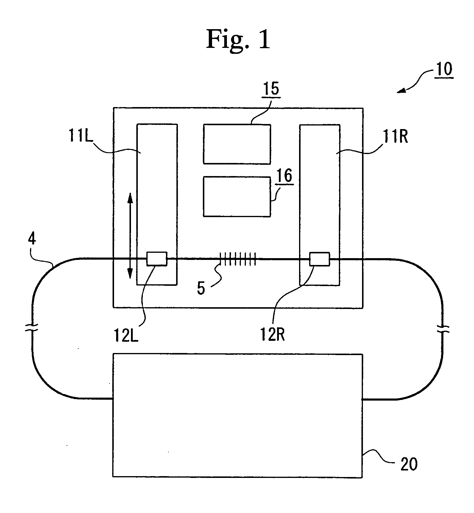
[0041] Examples of the optical fiber grating, the optical fiber grating manufacturing method, and the optical fiber grating manufacturing apparatus of the present invention will be explained referring to FIG. 1 to FIG. 8.

[0042] First, an example of the optical fiber grating manufacturing apparatus of the present invention will be explained.

[0043]FIG. 1 is a schematic drawing for explaining the optical fiber grating manufacturing apparatus of the present invention, and as an embodiment, shows the case therein the optical fiber grating part is formed.

[0044] In FIG. 1, the optical fiber 4 is anchored by the fiber clamps 12R and 12L disposed on the automatic stages 11R and 11L provided on both sides of the manufacturing apparatus 10. At the center of the manufacturing apparatus 10, a heating apparatus 15 such as a heater and an ultraviolet irradiation apparatus 16 are disposed, the optical fiber is moved vertically parallel to the ultraviolet irradiating apparatus 16 and the heating ...


PUM

PropertyMeasurementUnit
wavelengthaaaaaaaaaa
outer diameteraaaaaaaaaa
refractive indexaaaaaaaaaa

Abstract

The invention provides a method and apparatus that precisely and efficiently improves the optical properties of an optical fiber grating. Preferably hydrogen loading processing, grating formation processing that forms a grating part by irradiation with ultraviolet light at a predetermined period, and preferably dehydrogenation, adjusting the optical properties by a suitable combination of uniform ultraviolet irradiation processing that irradiates the grating part as a whole with ultraviolet light and heat trimming processing, and finally heat aging is carried out.

Description

[0001] This application claims priority of a prior application Ser. No. 09 / 929,934, filed Aug. 15, 2001BACKGROUND OF THE INVENTION [0002] 1. Field of the Invention [0003] The present invention relates to a manufacturing method for an optical fiber grating used in an optical communication system (hereinbelow, referred to simply as an “optical fiber grating), and in particular, an optical fiber grating, a manufacturing method for the same, and a manufacturing apparatus for the same that allows fine adjustment of the optical properties of the optical fiber grating, and greatly improves the manufacturing yield. [0004] 2. Description of the Related Art [0005] An optical fiber grating is a device having the property of attenuating the light of a specific frequency by coupling it in a reflection mode, a cladding mode, or a radiation mode. A type that couples the light of a specific wavelength with the cladding mode or radiation mode in the same direction as the incident light is called a t...

Claims


Application Information

Patent Timeline
Patent Type & Authority Applications(United States)
IPC IPC(8): G02B5/18C03B25/00G02B5/26G02B6/02G02B6/10G02B6/124G02B6/34
CPCG02B6/02185
Inventor ISHII, YUUNAKAI, MICHIHIROOKUDE, SATOSHINISHIDE, KENJISHIMA, KENSUKE
Owner ISHII YUU
Learn More