
Compact high power alternator

a high-power, compact technology, applied in the field of machines, can solve the problems of impracticality of voltage regulation and control of individual windings, difficulty in using high-output alternators, and disadvantages of claw-type generators, and achieve the effect of facilitating cooling and increasing the surface area of windings

Inactive Publication Date: 2005-02-17
MAGNETIC APPL
View PDF14 Cites 96 Cited by
  • Summary
  • Abstract
  • Description
  • Claims
  • Application Information

AI Technical Summary

Benefits of technology

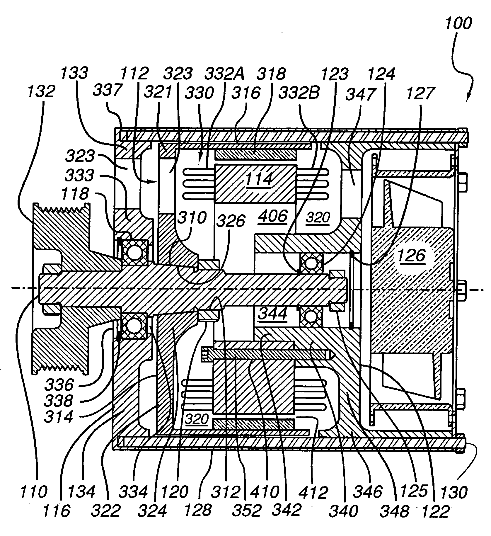
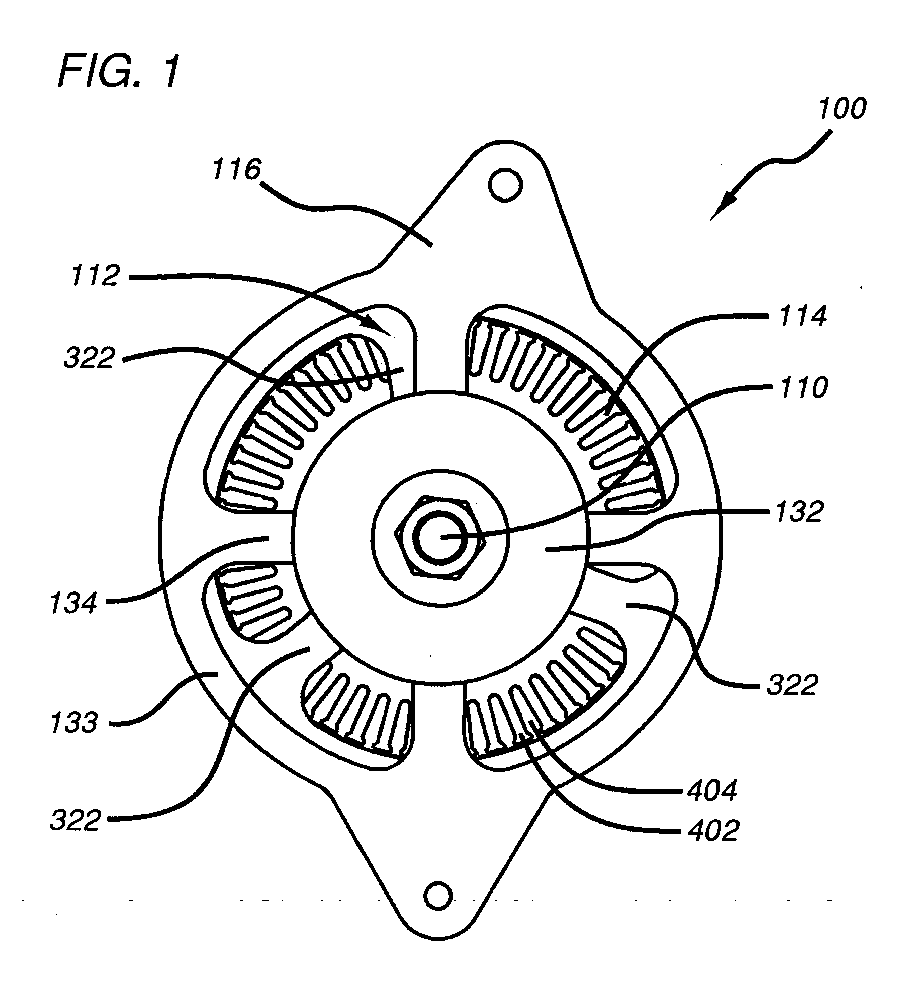
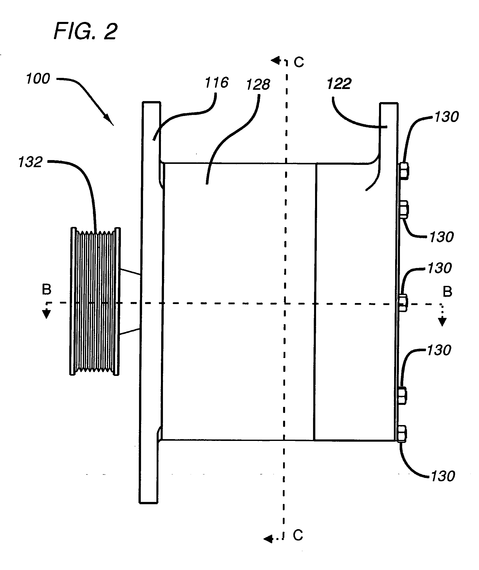
[0026] Various aspects of the invention provide a compact power conversion apparatus using permanent magnets that can accommodate not only the power levels, but also the space and ruggedness constraints imposed by use in vehicles. Another aspect of the invention provides a “remove and replace” high power alternator to retrofit existing vehicles.
[0027] Other aspects of the invention provide a compact high power conversion apparatus using permanent magnets in which rotor displacement is minimized, and which includes a mechanism to absorb unacceptable rotor displacement and prevent the rotor magnets from clashing with the stator.
[0033] In accordance with other aspects of the present invention, cooling is facilitated by one or more of: loosely wrapping winding end turns to, in effect, increase the surface area of the windings; establishing a directed airflow over at least a portion the stator windings, (preferably through loosely wrapped end turns of the windings); directing a portion of the airflow over elements in thermal contact with the magnets; providing airflow from a source that is asynchronous with respect to the shaft on which the rotor is mounted, e.g. an electric fan; and directing a flow of coolant fluid into thermal contact with the winding end turns.

Problems solved by technology

Accordingly, space constraints in vehicles tend to make such alternators difficult to use in high output, e.g., 5 kW, applications, such as for powering air conditioning, refrigeration, or communications apparatus.
In addition, claw-type generators are also disadvantageous in that voltage regulation is by modulating the rotating field.
Accordingly, voltage regulation and control of individual windings is impractical.
In addition, the claw-pole type rotors, carrying windings, are relatively heavy (often comprising as much as half of the total weight of the alternator) and create substantial inertia.
Such inertia, in effect, presents a load on the engine each time the engine is accelerated.
This tends to decrease the efficiency of the engine, causing additional fuel consumption.
In addition, such inertia can be problematical in applications such as electrical or hybrid vehicles.
The use of such electrical control and drive systems tends to increase the demand on the electrical power system of the vehicle.
Typically only a limited amount of space is provided within the engine compartment of the vehicle to accommodate the alternator.
Unless a replacement alternator fits within that available space, installation is, if possible, significantly complicated, typically requiring removal of major components such as radiators, bumpers, etc. and installation of extra brackets, belts and hardware.
With such close spacing / tolerances, the permanent magnet alternators are particularly susceptible to destructive interference (clashing) between magnets and stator as a result of displacement of the rotor caused by external forces acting on the alternator.
The tapered connection tends to center the attachment on the shaft, however, the attachment on the end of the shaft, is, in effect, cantilevered and susceptible to vibrational oscillations.
In addition, the heat generated by compact high power alternators can also be problematical.
Permanent magnets are particularly susceptible to damage due to overheating; under high load, high temperature conditions, such magnets can become demagnetized.
Similarly, the electronic components employed in the controller are susceptible to heat damage.
However, in various automotive applications, significant heat is generated at low rpm.
The reduction in both mass and overall diameters of these alternators tends to make the use of conventional cooling methods impractical.
For example, operation of a vehicle tends to generate forces perpendicular to the axis of the rotor that are sometimes sufficient to cause the rotor and stator to clash.
The rotor and stator are separated only by a small air gap, and the external forces tend to cause transverse movement of the rotor in excess of the air gap then there will be striking interference.

Method used


Image

  • Compact high power alternator
  • Compact high power alternator
  • Compact high power alternator

Examples


embodiment 329

[0089] However, it is advantageous, in applications employing control systems dependant on synchronization with the output, to have a power output wave with a particular waveform, e.g., sloping sides, to enhance control timing. This can be accomplished by establishing progressive (gradual) interaction between the rotor magnets and core teeth. Such progressive interaction can be provided by, for example, by utilizing teeth and slots with an edge skewed with respect to magnets 318, e.g., manifesting a generally helical shape. In a laminar core such teeth and slots can be formed using a slight and progressive radial skewing of each successive lamination so that the net effect after welding or epoxying is a lamination stack with a predetermined offset in the radial position of a given tooth from the front face of the lamination stack to the rear face. In the preferred embodiment, the offset is the equivalent of one tooth (e.g., the “th” tooth on the front face is aligned with tooth “n+1...

first embodiment

[0147] Referring to FIG. 12, a sealed alternator 1200 comprises: shaft 110; a sealed front end plate 1202; front bearings 118; stator 114; a forward facing rotor 1204; jam nut 120; an internal fan 1206; rear bearing 124; a sealed rear endplate 1208; a heat exchanger 1210; an external fan 1212 and a fan housing 1213 with an air intake 1214. (In this embodiment, tie rods 130 (not shown) may be disposed externally, as illustrated in FIG. 4) Front end plate 1202 suitably includes a stepped central hub 1214 (generally analogous to rear endplate hub 340 in the embodiment of FIG. 3) for mounting and locating front bearing 118, and stator core 328. Tapered portion 310 of shaft 110 is disposed at a predetermined axial distance from front end plate 1202 (generally corresponding to the axial length of rotor 1204). Rotor 1204 is essentially the same as rotor 112, but with the tapered portion of hub 324 reversed to accommodate a forward facing disposition of rotor 112. As in the embodiment of FI...

embodiment 1400

[0153] In some instances, it may be desirable to employ pressurized external air from a source located remotely from sealed alternator unit. Such an embodiment 1400 is shown in FIG. 14. Sealed alternator 1400 is substantially similar to alternator 1200 except that instead of being driven by a dedicated external fan 1212, alternator 1400 employs a rear housing 1402, the interior of which communicates with heat exchanger exterior channels 1228, cooperating with a plenum 1404 and a suitable remote pressurized air source, such as a remote fan 1406. External air flow 1234 is supplied by remote fan 1406, directed through a plenum 1404, through the interior of housing 1402 and channels 1228, and ultimately exiting through outlet 1224.

[0154] An alternative embodiment of the present invention particularly adapted for use in sandy, wet, or otherwise harsh conditions, employs a locally sealed alternator cooperating with a double walled snorkel to provide a cooling air from remote, less harsh s...


PUM


Abstract

An apparatus for converting between mechanical and electrical energy, particularly suited for use as a compact high power alternator for automotive use and “remove and replace” retrofitting of existing vehicles. The apparatus comprises a rotor with permanent magnets, a stator with a winding, and a cooling system. Mechanisms to prevent the rotor magnets from clashing with the stator by minimizing rotor displacement, and absorbing unacceptable rotor displacement are disclosed. The cooling system directs coolant flow into thermal contact with at least one of the winding and magnets, and includes at least one passageway through the stator core. Various open and closed cooling systems are described. Cooling is facilitated by, for example, loosely wrapping the winding end turns, use of an asynchronous airflow source, and / or directing coolant through conduits extending through the stator into thermal contact with the windings.

Description

RELATED APPLICATIONS [0001] This application claims priority to U.S. Provisional Application Ser. No. 60 / 486,831, filed Jul. 10, 2003, by inventors Charles Y. Lafontaine and Harold C. Scott.BACKGROUND OF THE INVENTION [0002] The present invention relates to machines for converting between mechanical and electrical energy, and in particular to a compact high power alternator using permanent magnets suitable for automotive use. [0003] An alternator typically comprises a rotor mounted on a rotating shaft and disposed concentrically relative to a stationary stator. Alternatively, a stationary rotor may be positioned concentrically within a rotating stator. An external energy source, such as a motor or turbine, commonly drives the rotating element, directly or through an intermediate system such as a pulley belt. Both the stator and the rotor have a series of poles. Either the rotor or the stator generates a magnetic field, which interacts with windings on the poles of the other structur...

Claims


Application Information

Patent Timeline
Patent Type & Authority Applications(United States)
IPC IPC(8): H02K1/18H02K1/27H02K1/30H02K7/09H02K9/06H02K9/08H02K9/19H02K11/04
CPCH02K1/187H02K1/2786H02K1/30H02K7/09H02K9/06H02K7/088H02K11/048H02K21/22H02K2201/03H02K9/10H02K9/19H02K11/05H02K1/2791H02K1/18H02K1/27
Inventor LAFONTAINE, CHARLES Y.SCOTT, HAROLD C.
Owner MAGNETIC APPL
Learn More