
Plasma cutting apparatus and control unit thereof

a technology of plasma cutting and control unit, which is applied in the direction of electrical programme control, soldering apparatus,auxillary welding devices, etc., can solve the problems of reducing the value of arc current, gas flow rate or pressure, and the weakened plasma arc gas spraying during hole cutting compared with that during contour cutting, so as to improve the cutting quality of the product and improve the cutting quality. quality, the effect of high cutting speed

Active Publication Date: 2005-02-17
KOMATSU IND CORP
View PDF6 Cites 78 Cited by
  • Summary
  • Abstract
  • Description
  • Claims
  • Application Information

AI Technical Summary

Benefits of technology

The present invention relates to a plasma cutting apparatus that improves the quality of hole cutting in plasma arc cutting. The technical effects of the invention include reducing the impact of cutting delay on cutting quality, decreasing the adverse effects of gas spraying on cutting quality, and improving the cutting speed and quality of hole cutting. The control unit of the apparatus conducts control to achieve these technical effects by controlling the cutting state based on factors such as the shape of the product, the material type and thickness of the plate material, and the ratio of the hole diameter to plate thickness. The apparatus can also include an assist gas and a high cutting speed for certain hole diameters. Overall, the invention enhances the efficiency and quality of plasma arc cutting for hole cutting.

Problems solved by technology

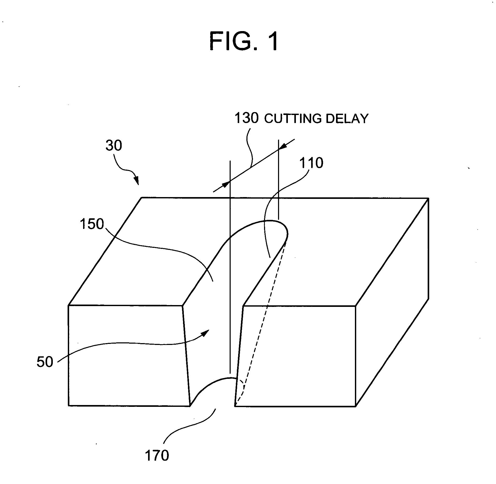
Furthermore, because the value of arc current and the plasma gas flow rate or pressure are decreased as the cutting speed is reduced, gas spraying of the plasma arc (A) during hole cutting is weakened by comparison with that during contour cutting.

Method used


Image

  • Plasma cutting apparatus and control unit thereof
  • Plasma cutting apparatus and control unit thereof
  • Plasma cutting apparatus and control unit thereof

Examples


Embodiment Construction

[0043]FIG. 4 shows the external appearance of all the body components of the plasma cutting apparatus of the first embodiment of the present invention.

[0044] In the plasma cutting apparatus 1, a cutting table (cutting stand) 2 for supporting a plate material (W) is disposed in the inner space of a rectangular frame 3. A gate-like traveling beam 4 is disposed so as to extend over the frame 3. A carriage 5 is disposed on the traveling beam 4, and a plasma torch 6 is mounted on the carriage 5.

[0045] The traveling beam 4 can travel, when driven by an X axis motor 7, in the X axis direction along an X axis rail 8 disposed in the longitudinal direction (X axis direction), and the carriage 5 can travel, when driven by an Y axis motor 9, in the Y axis direction along an Y axis rail 10 disposed on the traveling beam 4. Furthermore, the plasma torch 6 can move, when driven by a Z axis motor 11, in the up-down direction (Z axis direction) with respect to the carriage 5. Thus, by controlling ...


PUM

PropertyMeasurementUnit
bevel angleaaaaaaaaaa
cutting speedaaaaaaaaaa
pressureaaaaaaaaaa

Abstract

Cutting quality of the product, in particular, hole cutting quality, in plasma arc cutting is improved. A control unit, which controls a plasma cutting apparatus for cutting a product from a plate material by moving a plasma torch at a cutting speed along a cutting path corresponding to the product shape to cut the plate material, while supplying an arc current and a plasma gas to the plasma torch and forming a plasma arc from a nozzle of the plasma torch to the plate material, conducts control so that, when a hole is cut, a cutting speed is lower, a value of the arc current value is smaller, and a plasma gas flow rate or pressure is less than those when a contour is cut.

Description

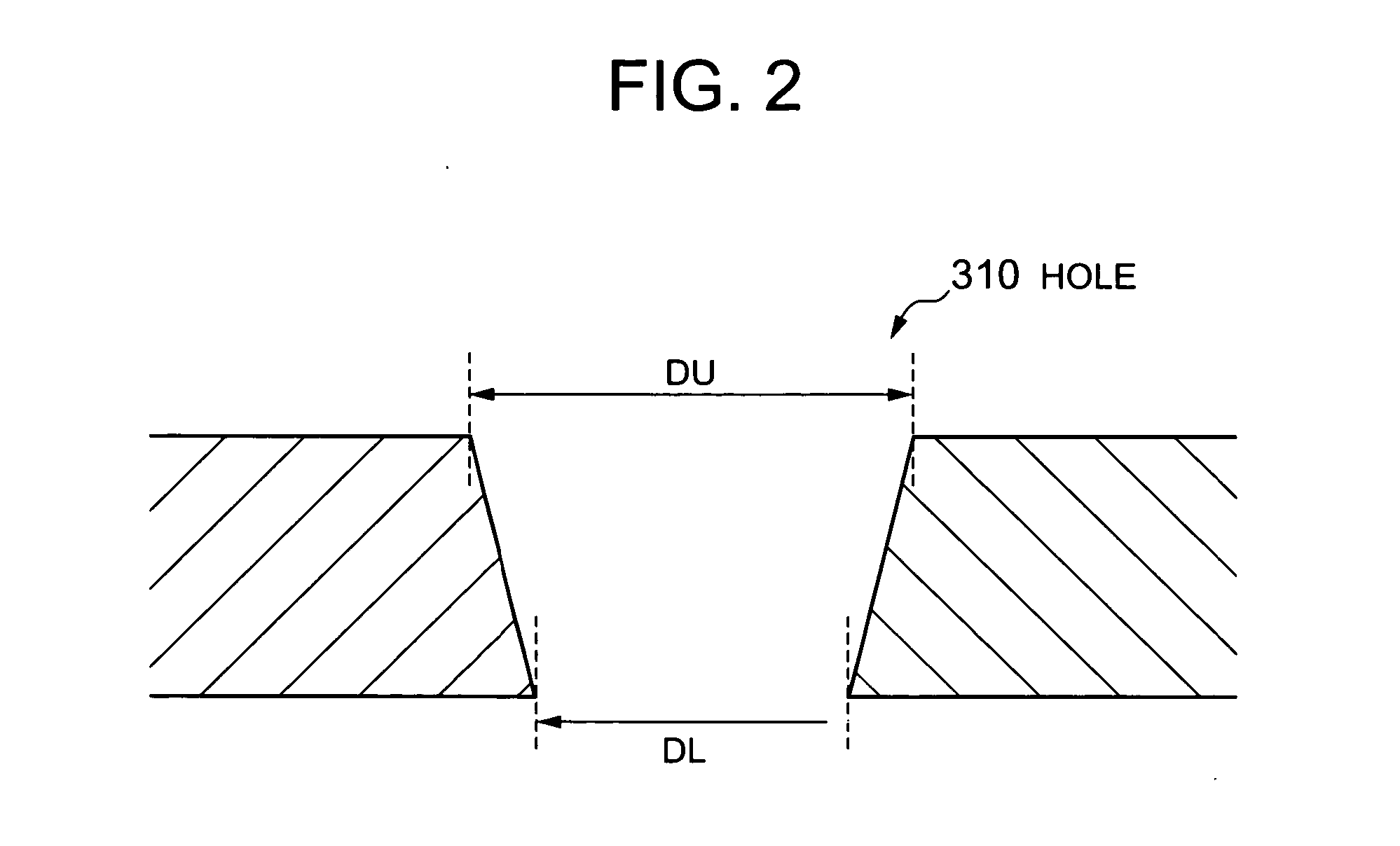
CROSS-REFERENCE TO RELATED APPLICATIONS [0001] This application relates to and claims priority from Japanese Patent Application No. 2003-150890 filed on May 28, 2003, the entire disclosure of which is incorporated herein by reference. BACKGROUND OF THE INVENTION [0002] 1. Field of the Invention [0003] The present invention relates to a plasma cutting apparatus for cutting products from a plate material and to a control unit thereof. [0004] 2. Description of the Related Art [0005] A plasma cutting apparatus for conducting plasma arc cutting by supplying a rotating flow of an assist gas into the zone around a rotating plasma arc, the flow rotating in the same direction as the arc, is known as a plasma cutting apparatus of this type. In plasma arc cutting, the cross section of the plate material assumes a tapered shape which narrows downward due to a plasma arc contraction, but in such a plasma cutting apparatus, the bevel angle formed by the cutting surface and the surface perpendicul...

Claims


Application Information

Patent Timeline
Patent Type & Authority Applications(United States)
IPC IPC(8): B23K10/00
CPCB23K10/006B23K10/00B23K37/0288G05B19/18Y10S29/013
Inventor YAMAGUCHI, YOSHIHIROKABATA, TETSUYA
Owner KOMATSU IND CORP
Learn More