
Method for scribing substrate of brittle material and scriber

a technology of brittle material and substrate, which is applied in the direction of glass making apparatus, manufacturing tools, welding/soldering/cutting articles, etc., can solve the problems of inability to form cracks, crack cr is uncontrollable, and the formation efficiency of vertical cracks is lowered

Inactive Publication Date: 2005-02-10
MITSUBOSHI DIAMOND IND CO LTD
View PDF7 Cites 25 Cited by
  • Summary
  • Abstract
  • Description
  • Claims
  • Application Information

AI Technical Summary

Benefits of technology

The present invention relates to a scribing method for a brittle material substrate that allows for the formation of a scribe line without causing damage to the substrate. The method involves heating the substrate with a laser beam along the scribe line formation line, while cooling the area close to the heated area. This results in a continuous heating and cooling process along the scribe line formation line, which prevents the substrate from softening or melting during the process. The method can be carried out using a single laser beam or two laser beams simultaneously. The invention also includes a scribing apparatus for carrying out the method. The technical effect of this invention is the ability to form a scribe line without causing damage to the substrate, which can be useful in various applications such as manufacturing electronic components or optical devices.

Problems solved by technology

As a result, a problem occurs in that the formation efficiency of the vertical crack is lowered.
The residual stress is released by the rapid heating by the laser spot LS, resulting in generation of the crack.
This crack CR is uncontrollable and cannot be formed along the scribe line formation line.

Method used


Image

  • Method for scribing substrate of brittle material and scriber
  • Method for scribing substrate of brittle material and scriber
  • Method for scribing substrate of brittle material and scriber

Examples


Embodiment Construction

[0037] Hereinafter, the present invention will be described by way of examples with reference to the attached drawings.

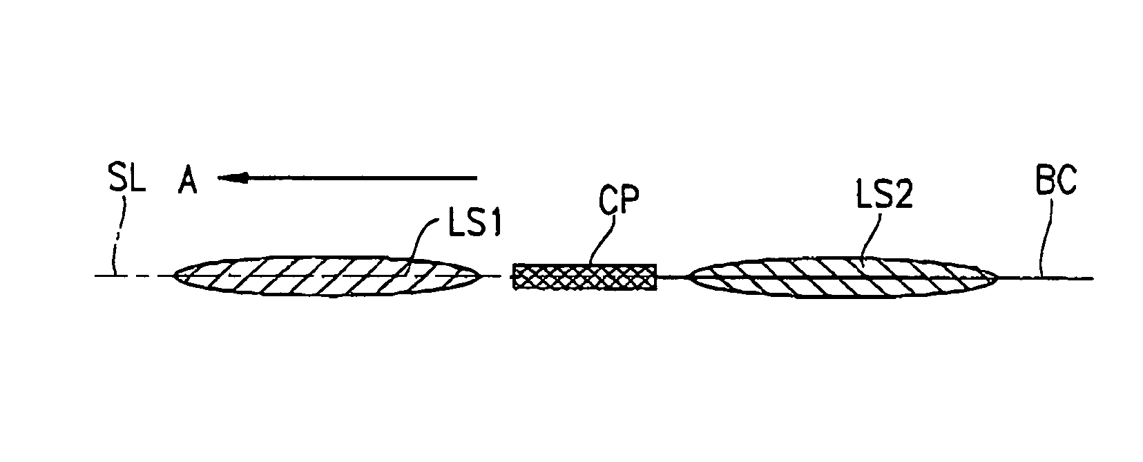
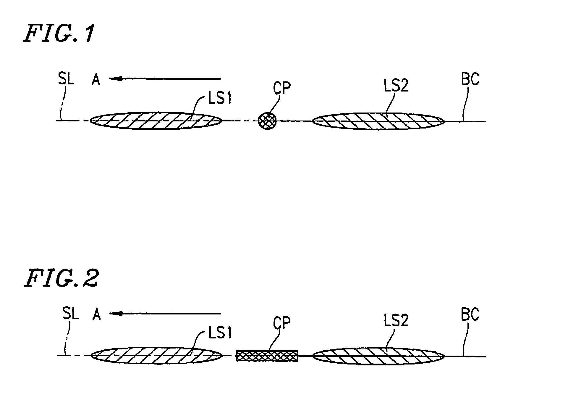
[0038] A scribing method for a brittle material substrate according to the present invention is carried out for example, to form a blind crack, which is to be a scribe line, on a mother glass substrate before the mother glass substrate is broken into a plurality of glass substrates included in an FPD such as a liquid crystal panel or the like. FIG. 1 is a schematic view of a state of a surface of the mother glass substrate when the scribing method is carried out.

[0039] As shown in FIG. 1, the surface of the mother glass substrate is irradiated with a laser beam, and thus a first laser spot LS1 is formed on the surface along a scribe line formation line SL. At one end of the scribe line formation line SL on the surface of the mother glass substrate, a notch is formed in the direction of the scribe line formation line SL.

[0040] The first laser spot LS1 has an ellip...


PUM

PropertyMeasurementUnit
diameteraaaaaaaaaa
diameteraaaaaaaaaa
temperatureaaaaaaaaaa

Abstract

A mother glass substrate is continuously heated by a first laser spot LS1 to a temperature which is lower than a softening point of the mother glass substrate, along a scribe line formation line SL on a surface of the mother glass substrate, along which a scribe line is to be formed, while an area close to the first laser spot LS1 is continuously cooled along the scribe line formation line SL; and an area which is close to the cooled area and is on an opposite side to the first laser spot LS1 is continuously heated by a second laser spot LS2 along the scribe line formation line SL to a temperature which is lower than the softening point of the mother glass substrate.

Description

TECHNICAL FIELD [0001] The present invention relates to a scribing method and a scribing apparatus for forming a scribe line on a surface of a substrate of a brittle material such as a glass substrate, a semiconductor wafer or the like used for a flat panel display (hereinafter, referred to as the “FPD”) in order to scribe and break the brittle material substrate. BACKGROUND ART [0002] In this specification, formation of a scribe line on a mother glass substrate of a liquid crystal display panel, belonging to glass substrates, which is a type of brittle material substrates, will be described. [0003] An FPD such as a liquid crystal display panel or the like, which includes a pair glass substrates assembled together, is produced as follows. A pair of large sized mother glass substrates are assembled together, and then each mother glass substrate is scribed and broken into glass substrates included in the FPD. For scribing and breaking each mother glass substrate, a scribe line is form...

Claims


Application Information

Patent Timeline
Patent Type & Authority Applications(United States)
IPC IPC(8): B23K26/073B23K26/38B23K26/40B28D1/22B28D5/00C03B33/09
CPCB23K26/0604B23K26/0736C03B33/093B28D1/221B28D5/0011B23K26/4075B23K26/40B23K2103/50B28D5/00
Inventor MATSUMOTO, MASATOGONOE, TOUGO
Owner MITSUBOSHI DIAMOND IND CO LTD
Learn More