
Robotic cart pulling vehicle

Active Publication Date: 2005-02-10
ST ENG AETHON INC
View PDF32 Cites 70 Cited by
  • Summary
  • Abstract
  • Description
  • Claims
  • Application Information

AI Technical Summary

Benefits of technology

[0025] The objects of the present invention are achieved with a robotic cart pulling vehicle including a positioning error reducing system for reducing accumulated error in the ded-reckoning navigational system according to the present invention. The positioning error reducing system includes at least one of a low load transfer point of the cart attaching mechanism, a floor variation compliance structure whereby the drive wheels maintain a substantially even distribution of load over minor surface variations, a minimal wheel contact surface structure, a calibration structure using at least one proximity sensor mounted on the robot body, and an electrical and mechanical connection between the cart and the robotic vehicle formed with a cart attaching post
[0028] A further modification in the robotic vehicle forming the positioning error reducing system for reducing accumulated error in the ded-reckoning navigational system is the wheel design for improved ded reckoning accuracy. The present wheel design is created to keep the variation in the wheel radius and the width between the wheels under 2%, or even 0.5%. The wheel design of the present invention is intended to minimize the contact patch width provided by the wheel as well as minimize the variation in the compression of the wheel relative to load on the vehicle. To accomplish this, the wheel is provided with a solid stiff circular core provided with an outer annular coating providing the tire tread. In cross-section, the tread may converge to an annular contact area of minimum width, other minimal width annular contact areas are also possible.

Problems solved by technology

The robotic courier has many disadvantages, the first of which is that it is overly expensive, and a second is that it is only useful for transporting materials that can fit in the associated cabinet installed with the robot.
The above discussed prior art does not effectively provide for a cart pulling or cart pulling robotic vehicle that would be useful for hauling materials on a variety of carts or wagons indoors.

Method used


Image

  • Robotic cart pulling vehicle
  • Robotic cart pulling vehicle
  • Robotic cart pulling vehicle

Examples


Embodiment Construction

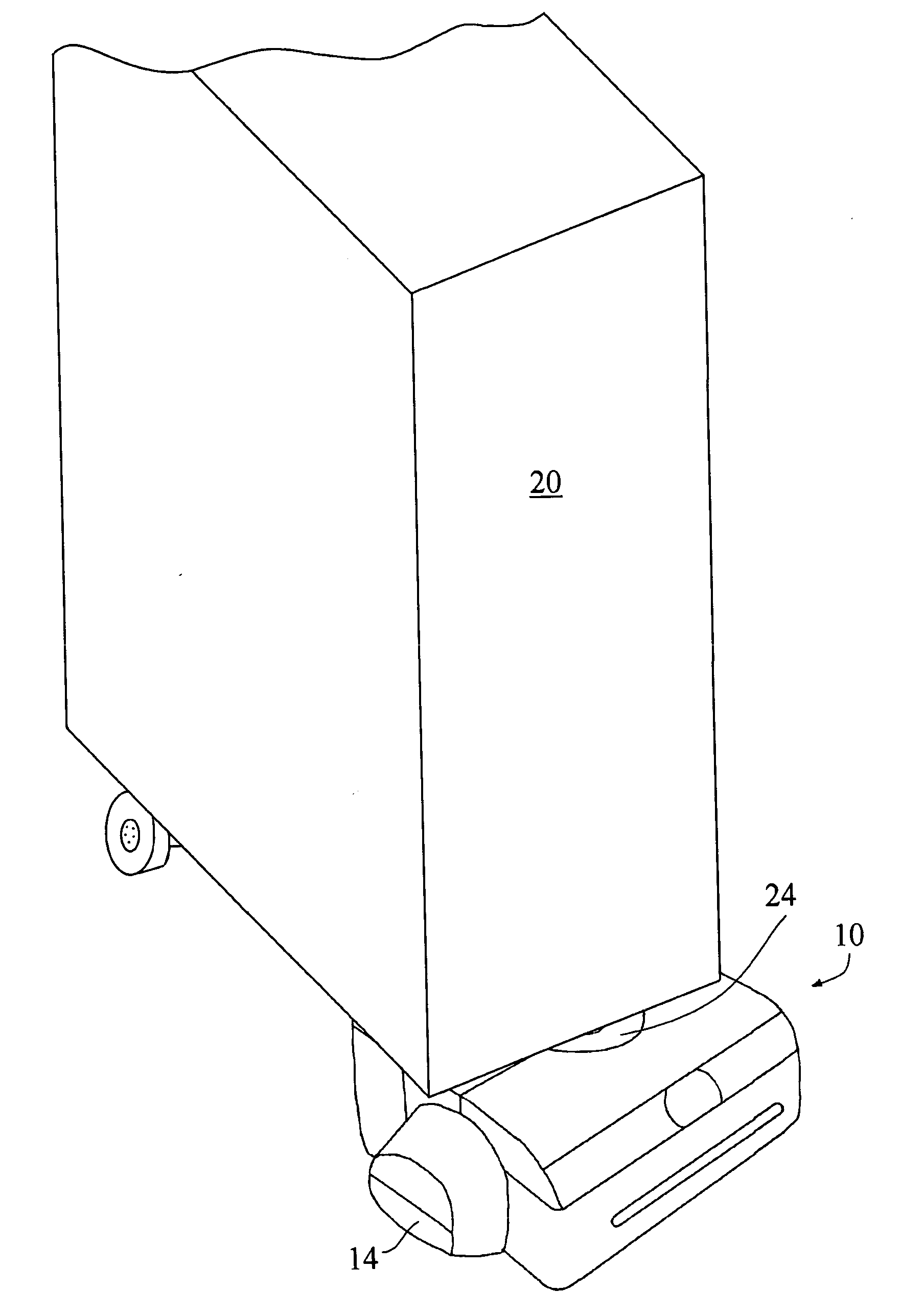
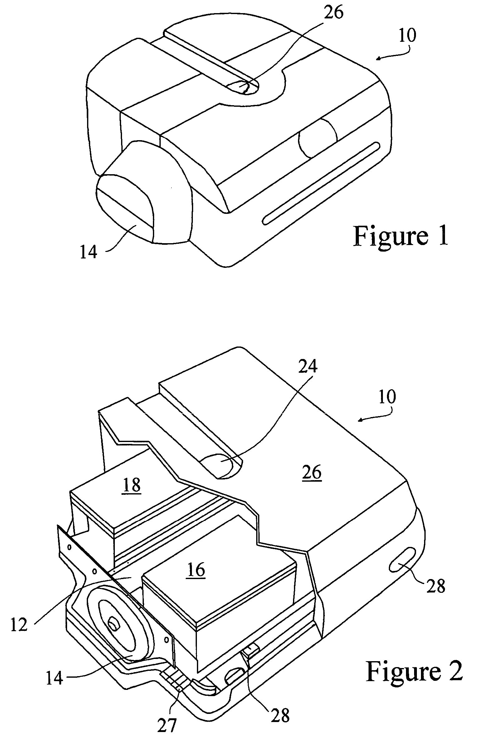
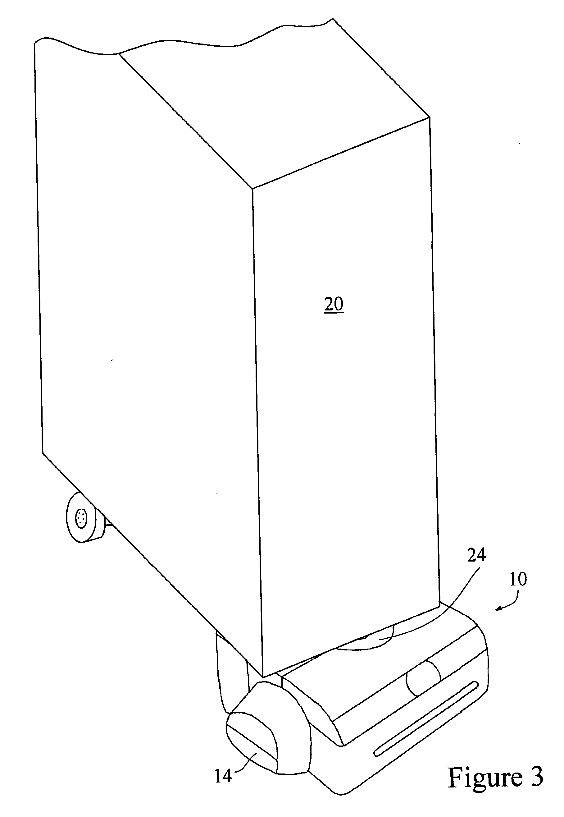
[0041] The robotic vehicle 10 or robot of the present invention is shown in FIGS. 1 and 2. The robotic vehicle 10 is essentially a chassis or body 12 with two co-axial driven wheels 14. The body 12 houses the circuit board or computer controller 16 for the vehicle 10. A battery pack 18 is also on the body 12 although the robotic vehicle 10 could also be powered through a battery on an attached cart or cart 20 being pulled by the robotic vehicle 10. A cart attachment mechanism 24 is centered on the body 12 midway between the wheels 14 essentially along and above the axels of the wheels 14. A housing 26 covers the body 12 and includes a collection of sensors 27 and 28 which are used for obstacle detection and correction of positioning and orientation error. Specifically, range sensors 27 are used for correction of positioning and orientation error as described below and sonar sensors 28 are used for obstacle detection as generally known in the art. The robotic vehicle 10 can have a va...


PUM


Abstract

A robotic cart pulling vehicle includes a positioning error reducing system for reducing accumulated error in the ded-reckoning navigational system. The positioning error reducing system including at least one of a low load transfer point of the cart attaching mechanism, a floor variation compliance structure whereby the drive wheels maintain a substantially even distribution of load over minor surface variations, a minimal wheel contact surface structure, a calibration structure using at least one proximity sensor mounted on the robot body, and a common electrical and mechanical connection between the cart and the robot vehicle formed by a cart attaching post.

Description

RELATED APPLICATIONS [0001] This application claims the benefit of pending provisional application Ser. No. 60 / 407,117 filed Aug. 30, 2002 entitled “Robotic Cart Pulling Vehicle” which is incorporated herein by reference in its entirety.BACKGROUND OF THE INVENTION [0002] 1. Field of the Invention [0003] The present invention relates to robotic cart pulling vehicles for automated hauling of materials indoors. More specifically, the present invention relates to a cart pulling deduced reckoning guided mobile robot system. [0004] 2. Background of the Invention [0005] Robotic and automated vehicles for delivering or transporting material indoors have been developed and utilized in a number of applications. One well-known application is the automated mail delivery vehicles and robots. An example of such a mail delivery vehicle is manufactured by the Mailmobile division of Bell and Howell. Rather than being an independent robotic vehicle, this is an automatic guided vehicle following a pre...

Claims


Application Information

Patent Timeline
IPC IPC(8): B62DB62D1/00B62D1/24G05D1/02
CPCG05D1/0242G05D1/0272G05D2201/0211G05D2201/0206G05D1/0274
Inventor THORNE, HENRY F.
Owner ST ENG AETHON INC
Learn More