
Hydrogen sulfide injection method for phosphor deposition

Inactive Publication Date: 2005-02-03
IFIRE IP CORP
View PDF12 Cites 25 Cited by
  • Summary
  • Abstract
  • Description
  • Claims
  • Application Information

AI Technical Summary

Benefits of technology

[0008] The method is particularly suitable for the deposition of phosphor compositions comprising thioaluminates, thiogallates or thioindates of elements from Group IIA and Group IIB of the Periodic Table of Elements, where the source material(s) include sulfides that contain at least some of the elements comprising the deposited phosphor films. The phosphors produced using the invention show increased stability and extended life as compared to phosphors made according to the methods of the prior art.

Problems solved by technology

The properties of the deposited phosphor films are sensitive to background concentrations of sulfur and oxygen species present in the deposition atmosphere that may detrimentally affect film performance.
Currently there is no reliable method to introduce hydrogen sulfide as a sulfur source for phosphor deposition at sufficiently high concentrations and sufficiently high reactive temperatures and energies in order to effectively and reproducibly provide a high luminance phosphor with stable operating characteristics.
However, these methods of hydrogen sulfide introduction do not fully overcome the tendency of the deposited phosphor to be unstable during operation.

Method used


Image

  • Hydrogen sulfide injection method for phosphor deposition
  • Hydrogen sulfide injection method for phosphor deposition
  • Hydrogen sulfide injection method for phosphor deposition

Examples


example 1

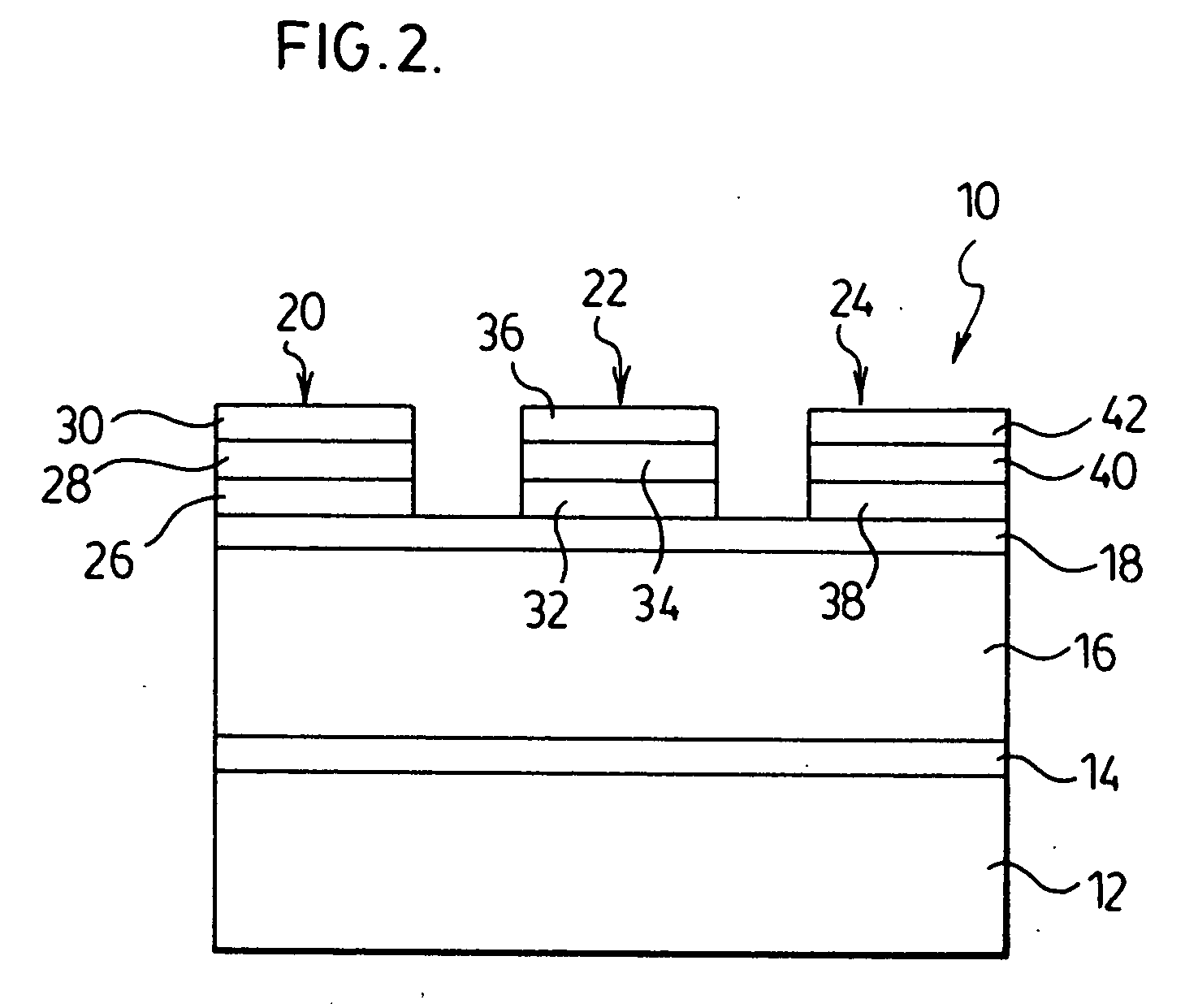
[0052] A thick film dielectric electroluminescent device was constructed incorporating thin film phosphor layers of barium thioaluminate activated with europium. The thick film substrate was a 5 cm×5 cm glass substrate having a thickness of about 2 mm. Onto this substrate was deposited a gold electrode, followed with a thick film high dielectric constant dielectric layer in accordance with the methods exemplified in Applicant's co-pending Provisional patent application Ser. No. 10 / 326,777 filed Dec. 19, 2002 (the disclosure of which is incoporated herein by reference in its entirety). A 100 nm to 200 nm thin film dielectric layer of barium titanate was deposited on top of the thick film dielectric layer using the sol gel technique described in Applicant's co-pending U.S. patent application Ser. No. 09 / 761,971 filed Jan. 17, 2001 (the disclosure of which is herein incorporated in its entirety).

[0053] A 600 nm thick barium thioaluminate phosphor film activated with about 3 atomic per...

example 2

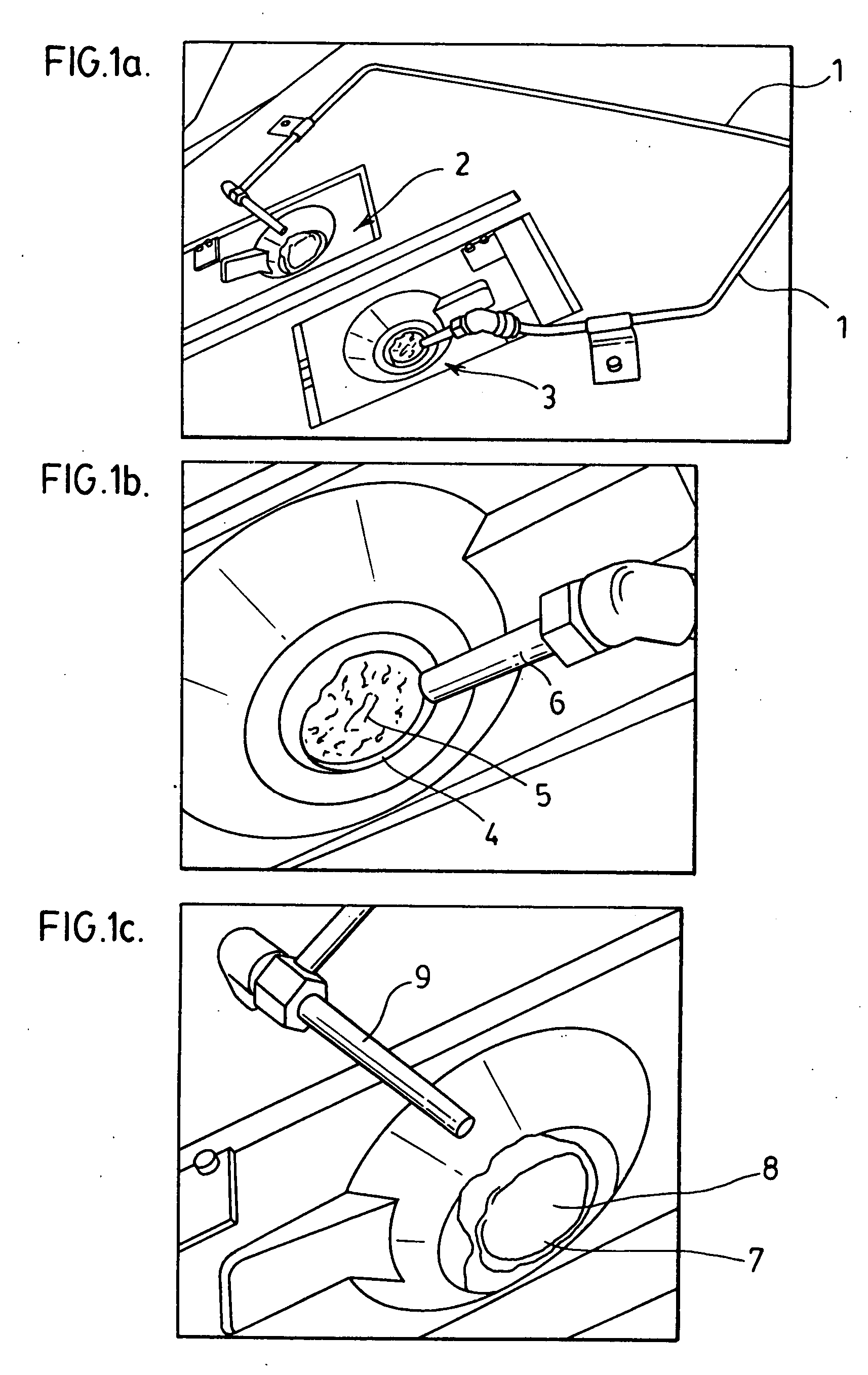
[0057] A device similar to that of Example 1 was constructed but incorporated the hydrogen sulfide injector of the present invention as shown in FIG. 1. The injector was used to provide a controlled concentrated source of hydrogen sulfide gas at a rate of 20 to about 60 sccm on the surface of the molten sulfide sources and in the environment of the electron beam. FIG. 4 shows the typical life of the device expressed as luminance versus operating time. The curve indicated by “H2S injected” shows a dramatic increase in lifetime to more than 500 hours for such the device compared to the lifetime of a device fabricated in accordance with Example 1.

[0058] The phosphor film was analyzed by energy dispersive X-ray analysis to determine concentrations of elemental species in the phosphor film. The film had an aluminum to barium ratio of about 3 to 7 with the film containing about 9.9 atomic percent oxygen and 41 atomic percent sulfur. The use of the hydrogen sulfide injector increased the ...

example 3

[0059] A device similar to that of Example 1 was constructed but instead of annealing the device in nitrogen immediately following phosphor deposition the device was annealed in air. FIG. 5 shows the operation lifetime for such a device expressed as luminance versus operating time. The curve marked “no H2S injector” shows that the operational life, defined as time to half brightness, was about 10 hrs.


PUM

PropertyMeasurementUnit
Lengthaaaaaaaaaa
Flow rateaaaaaaaaaa
Flow rateaaaaaaaaaa

Abstract

The invention is a method of vacuum evaporation of a multi-element sulfur bearing thin film compositions onto a substrate. The method comprises targeting a source of gas or vapour sulfur species at one or more source materials that make up at least part of the thin film composition during evaporation of the source materials. The sulfur species is heated to a high temperature as it reaches the one or more source materials and there is a chemical interaction of the sulfur species with evaporant from the one or more source materials during deposition of said thin film composition. The method is particularly useful for the deposition of phosphors for full colour ac electroluminescent displays employing thick film dielectric layers with a high dielectric constant.

Description

FIELD OF THE INVENTION [0001] The present invention relates to a method for the deposition of multi element sulfur-bearing thin film phosphor compositions. More specifically, the invention is a method for the deposition of a sulfur-bearing phosphor material where hydrogen sulfide is injected towards at least one of the deposition source materials that make up the deposited phosphor film. The method is particularly useful for the deposition of phosphors for full colour ac electroluminescent displays employing thick film dielectric layers with a high dielectric constant. BACKGROUND OF THE INVENTION [0002] Thick film dielectric electroluminescent devices as exemplified by U.S. Pat. No. 5,432,015 (the entirety of which is incorporated herein by reference) are typically fabricated on ceramic or glass substrates and provide superior resistance to dielectric breakdown, as well as a reduced operating voltage compared to thin film electroluminescent (TFEL) displays fabricated on glass substr...

Claims


Application Information

Patent Timeline
IPC IPC(8): C09K11/77C23C14/00C23C14/06C23C16/06H05B33/14
CPCC09K11/7774H05B33/14C23C14/0623C23C14/0021C09K11/7734
Inventor XIN, YONGBAOACCHIONE, JOEHUNT, TERRY
Owner IFIRE IP CORP
Learn More