
Receiver based decision feedback equalization circuitry and techniques

Active Publication Date: 2005-02-03
SYNOPSYS INC
View PDF8 Cites 20 Cited by
  • Summary
  • Abstract
  • Description
  • Claims
  • Application Information

AI Technical Summary

Benefits of technology

[0015] In one embodiment, the receiver may include adaptive circuitry, coupled to the second input of each data slicers, to adjust the first and/or second slicer levels in accordance with the performance of the receiver or to change the first and/or second data

Problems solved by technology

The increase in data rate presents a challenge to maintain, enhance or optimize the ability to recover the transmitted signal and thereby the information contained therein.
In general, increasing the rate of transfer of data tends to adversely impact the fidelity of the communications.
Conventional decision feedback equalization circuitry is typically quite complicated to implement as well as computationally intensive.
As such, the implementation of conventional decision feedback equalization is often difficult and expensive.

Method used


Image

  • Receiver based decision feedback equalization circuitry and techniques
  • Receiver based decision feedback equalization circuitry and techniques
  • Receiver based decision feedback equalization circuitry and techniques

Examples


Embodiment Construction

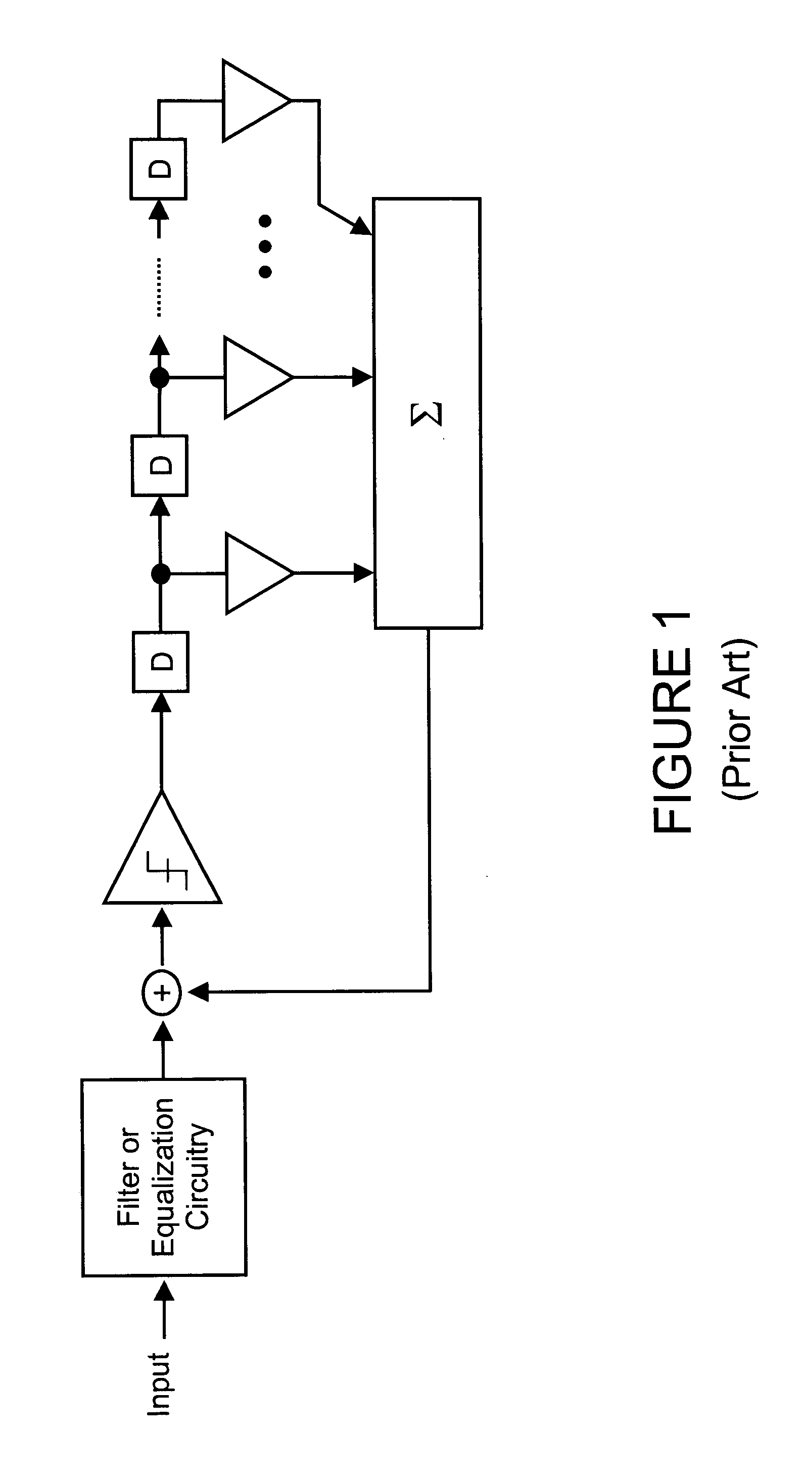
[0037] There are many inventions described and illustrated herein. In one aspect, the present invention is directed to a technique of, and circuitry and system for enhancing the performance of data communication systems using receiver based decision feedback equalization circuitry. In one embodiment, the equalization circuitry and technique employs a plurality of data slicers (for example, a set of two) to receive an analog input and output a binary value based on a reference or slicer level and a plurality of phase slicers (for example, a set of three) sampling a half symbol interval offset in time from the data slicers for timing recovery. The output of the data slicers is provided to logic circuitry to determine whether the analog input was a binary or logic high or binary or logic low. In those instances where the data slicers “agree” and both indicate either a high or a low, the logic circuitry outputs the corresponding binary value. In those instances where the data slicers do...


PUM


Abstract

In one aspect, the present invention is directed to a technique of, and circuitry and system for enhancing the performance of data communication systems using receiver based decision feedback equalization circuitry. In one embodiment, the equalization circuitry and technique employs a plurality of data slicers (for example, two) to receive an analog input and output a binary value based on the reference or slicer level. The output of the data slicers is provided to logic circuitry to determine whether the analog input was a binary high or binary low. In those instances where the data slicers “agree” and both indicate either a high or a low, the logic circuitry outputs the corresponding binary value. In those instances where the data slicer do not “agree”—that is, where one data slicer indicates the input to be a binary or logic high value and the other data slicer indicates the input to be a binary or logic low value, in one embodiment, the logic circuitry outputs the complement of the previous binary value. In another embodiment, the logic circuitry selects the output from the slicer that changed its output from the previous binary value. In yet another embodiment where the slicers do not “agree”, the logic circuitry selects the decision of the data slicer with higher slicer value if the previous binary value was “high”, or selects the decision of the data slicer with the lower slicer value if the previous binary value was “low”. The data slicers employ slicer levels that may be fixed, pre-programmed, predetermined, preset, changed, modified, optimized, enhanced and / or programmed or re-programmed (for example, adaptively) before or during operation of the decision feedback equalization circuitry.

Description

BACKGROUND OF THE INVENTION [0001] This invention relates to systems and techniques that are used to enhance the performance of data communication systems; and more particularly, in one aspect, to enhance the performance of data communication systems (for example, communication systems implemented in wired type environments such as microstrip, stripline, printed circuit board (e.g., a backplane) and cable using receiver based equalization. [0002] Communications systems are continuing to increase the rate at which data is transmitted between devices. The increase in data rate presents a challenge to maintain, enhance or optimize the ability to recover the transmitted signal and thereby the information contained therein. In general, increasing the rate of transfer of data tends to adversely impact the fidelity of the communications. [0003] A technique to address that impact on the communications is to employ equalization circuitry in, for example, the transmitter, receiver, or both th...

Claims


Application Information

Patent Timeline
IPC IPC(8): H03K5/159H04L25/03
CPCH04L2025/0349H04L25/03057
Inventor STONICK, JOHN T.SONNTAG, JEFFREY L.WEINLADER, DANIEL KEITH
Owner SYNOPSYS INC
Learn More