Controlled transmissions across packet networks

a packet network and transmission technology, applied in the field of packet communication, can solve the problems of not meeting the network, one or both telecommunication providers might get shortchanged, and add to the complexity

Inactive Publication Date: 2005-02-03
AMERICAN TELEPHONE & TELEGRAPH CO
View PDF43 Cites 9 Cited by
  • Summary
  • Abstract
  • Description
  • Claims
  • Application Information

AI Technical Summary

Benefits of technology

The prior art problems are overcome and an advance in the art is achieved by eliminating the need for a call agent to send mapping information directly to edge switches. This is achieved by all edge nodes mapping received packet addresses in accordance with a predetermined function. The mapping according to the function may change at regular intervals, or upon the occurrence of specifi

Problems solved by technology

However, neither Verizon nor PacTel own a packet network that extends from New York to Los Angeles, and their networks do not even meet.
Otherwise, one or both of the telecommunication providers might get shortchanged.
However, as indicated above, MTAs connect directly to the packet network, and those are not under control of the telecommunication service provider.
There are a number of problems with this solution.
This communication must take place in each of these separate networks, adding to the complexity.
Reliably establishing the communicati

Method used


Image

  • Controlled transmissions across packet networks
  • Controlled transmissions across packet networks
  • Controlled transmissions across packet networks

Examples


Embodiment Construction

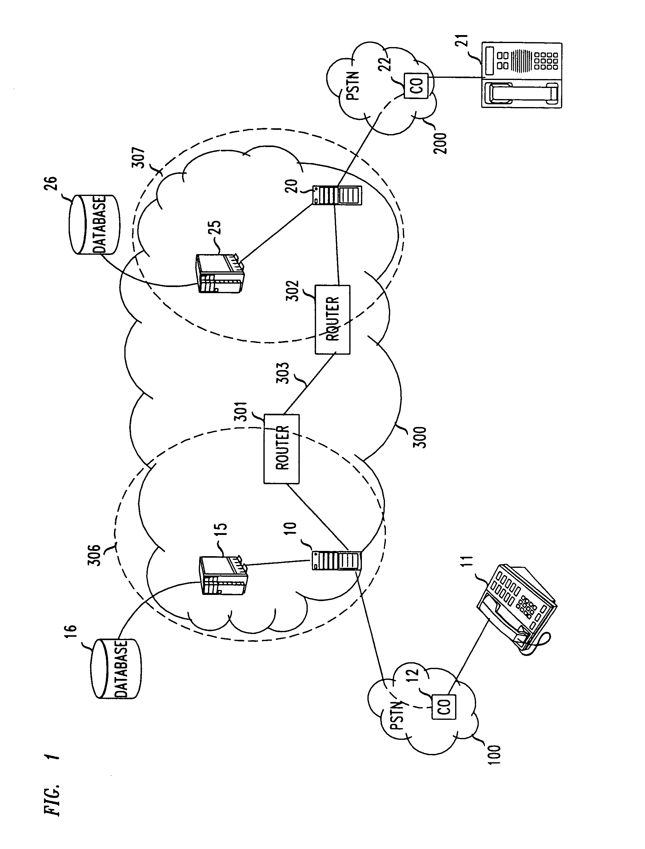
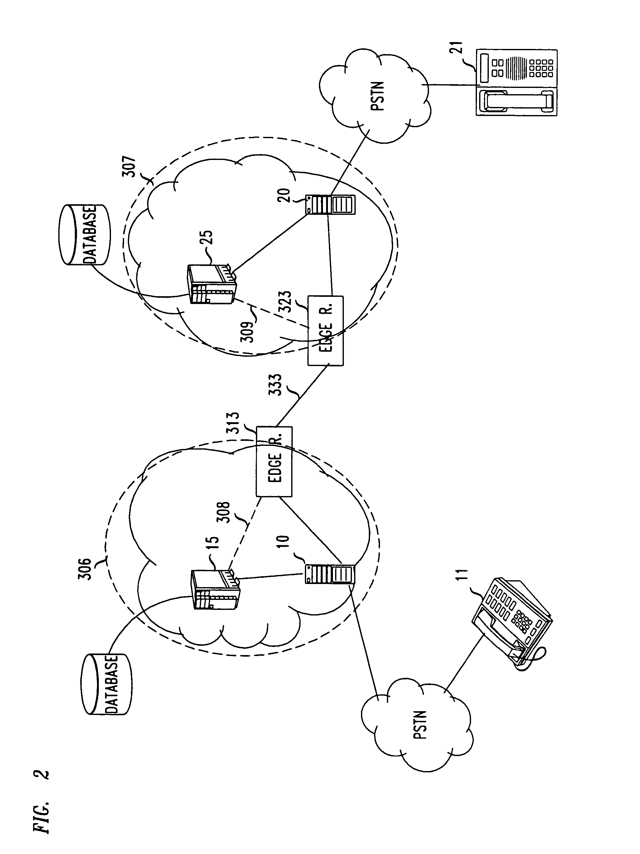
FIG. 3 illustrates a packet network arrangement that comports with the principles of this invention; and with respect to those principles, it is similar to the FIG. 1 arrangement. For illustrative purposes, however, instead of a single network as shown in FIG. 1, FIG. 3 depicts an ATM network 310, and an ATM network 320; instead of gateway 10, PSTN 100 and user 11, there is an MTA 13 that is connected to switch 314 within network 310; and instead of gateway 20, PSTN 200 and user 12, there is an MTA 23 that is connected to switch 324 within network 320.

It is noted that the switches in ATM networks perform essentially the same function as do the routers in IP networks. In this disclosure, therefore, the term “node” is used to subsume both a router and a switch.

For convenience, it may be assumed that MTA 13 is in New York and network 310 is owned by Verizon, that MTA 23 is in Los Angeles and network 320 is owned by PacTel, and that the connection between networks 310 and 320 is eith...


PUM


Abstract

Control over the movement of packets is exercised by edge nodes of a network mapping the addresses of incoming packets in accordance with a prespecified functional mapping P. Remote sources of packets are provided address information that is mapped with a prespecified functional mapping Q, where mappings P and Q are such that P(Q(j)=j. The mapping change at regular intervals, or upon the occurrence of specified events, and with each change, the communicating the remote source is provided with a different mapped address to be used.

Description

BACKGROUND This invention relates to packet communication and, more particularly, to fee-based communication across multiple packet networks. Most US telecommunication providers currently employ packet networks to transport both voice and data signals. Such a network, shown in FIG. 1, transports information in packets that are routed from router to router (e.g. from router 301 to router 302), via links (e.g., 303), from an originating point in the network to a terminating point in the network. FIG. 1 depicts a typical arrangement for coupling a user 11 in one location (for example, New York) to a user 12 in another location (for example, Los Angeles). User 11 is connected to a local circuit-switched network 100 in New York (e.g., Verizon), and more particularly to a central office 12 within network 100. Similarly, user 21 is connected to a local circuit-switched network 200 in Los Angeles (e.g., PacTel), and more particularly to a central office 22 within network 200. When a call...

Claims


Application Information

Patent Timeline
IPC IPC(8): H04L29/06H04L29/12
CPCH04L29/06H04L29/06027H04L29/12009H04L29/12433H04L65/80H04L61/2539H04L61/35H04L63/0407H04L29/12783H04L61/00H04L9/40H04L65/1101
Inventor BROWN, JOHN CARLRUSSELL, LARRY ARNISE
Owner AMERICAN TELEPHONE & TELEGRAPH CO
Why Eureka
Try Eureka