Counter-stream-mode oscillating-flow heat transport apparatus
a heat transport apparatus and counter-stream mode technology, applied in lighting and heating apparatus, cooling/ventilation/heating modification, semiconductor devices, etc., can solve the problems of heat transport capability decline and heat transport capacity decrease, and achieve the effect of preventing heat transport capability degradation
- Summary
- Abstract
- Description
- Claims
- Application Information
AI Technical Summary
Benefits of technology
Problems solved by technology
Method used
Image

Examples
first embodiment
[0059] [First Embodiment]
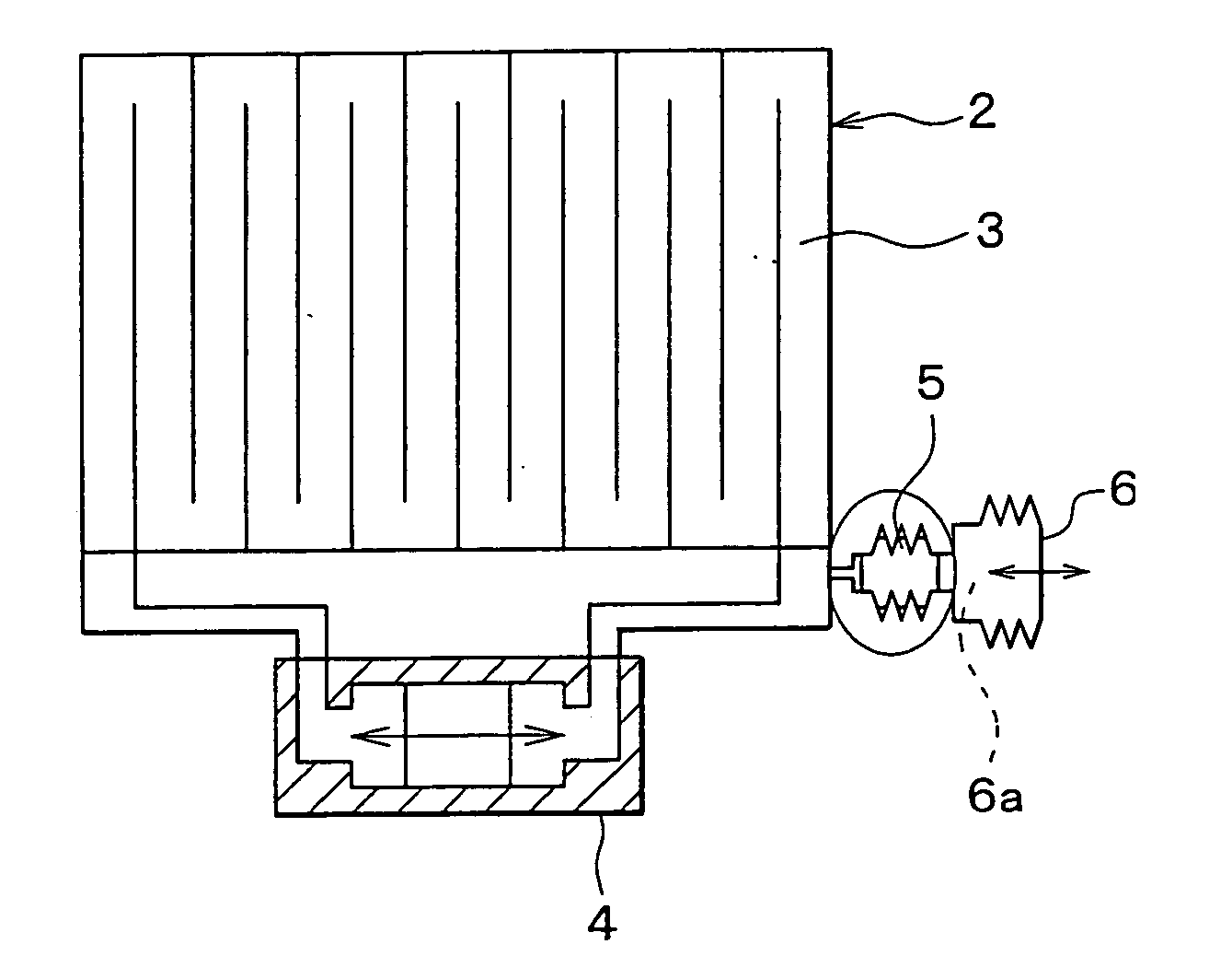
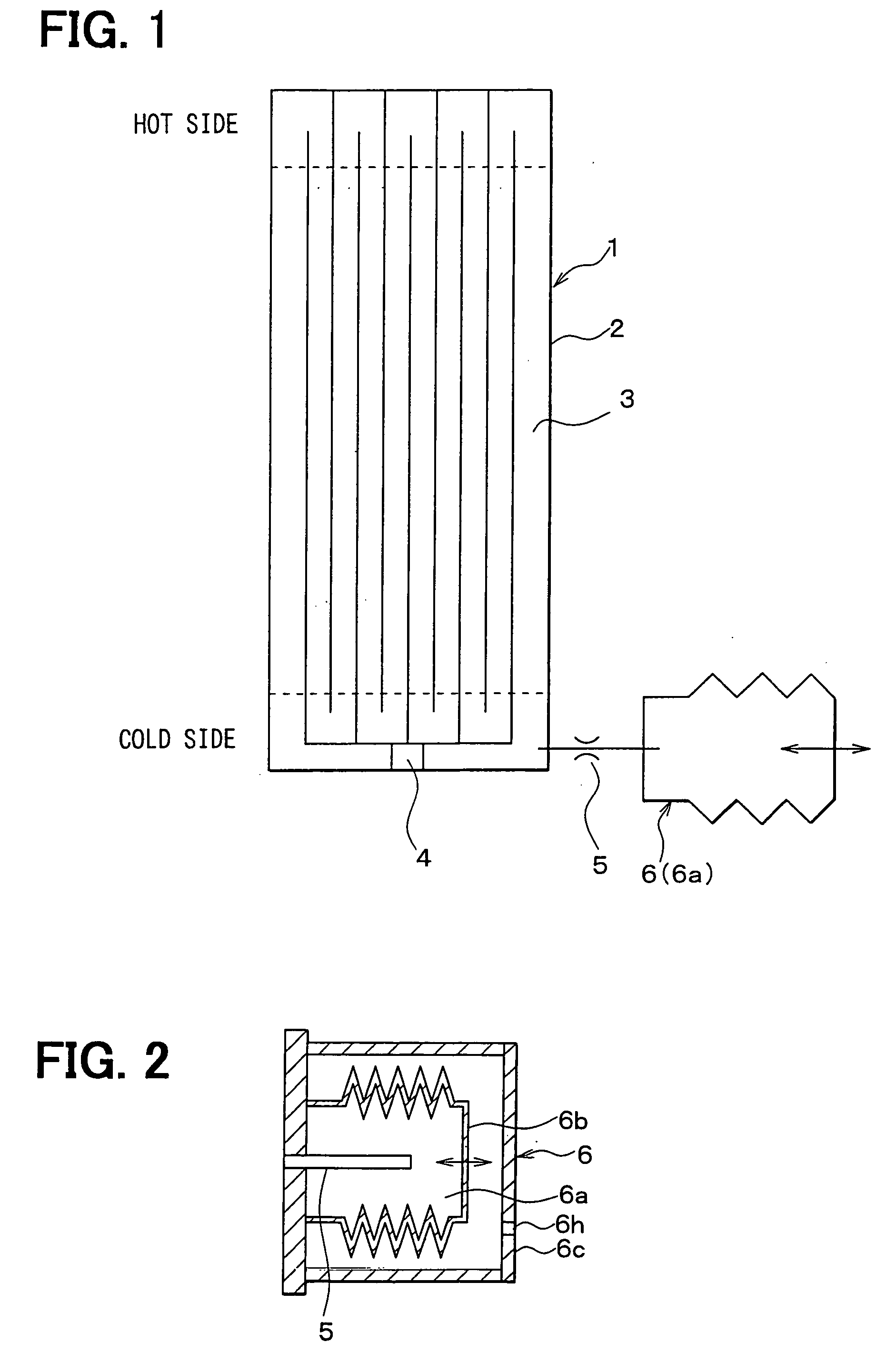
[0060] This embodiment is implemented by the present invention being applied to a cooling device for use with electronic components. FIG. 1 is a schematic view showing a counter-stream-mode oscillating-flow heat transport apparatus 1 according to this embodiment. FIG. 2 is a partially enlarged cross-sectional view showing a buffer tank 6.
[0061] Referring to FIG. 1, a heat transport device assembly 2 formed generally in the shape of a swath of plate has meandering flow paths 3 filled with a liquid, and includes a target to be cooled or a heating element (not shown) with a heat source on a plate face generally at a longitudinal end (at the upper end in the figure). The configuration of the heat transport device assembly 2 will be described later.
[0062] In this embodiment, the heating element is intended to represent electronic components such as integrated circuits for use in computers. The heat transport device assembly 2 is also provided with a heat sink (...
second embodiment
[0076] [Second Embodiment]
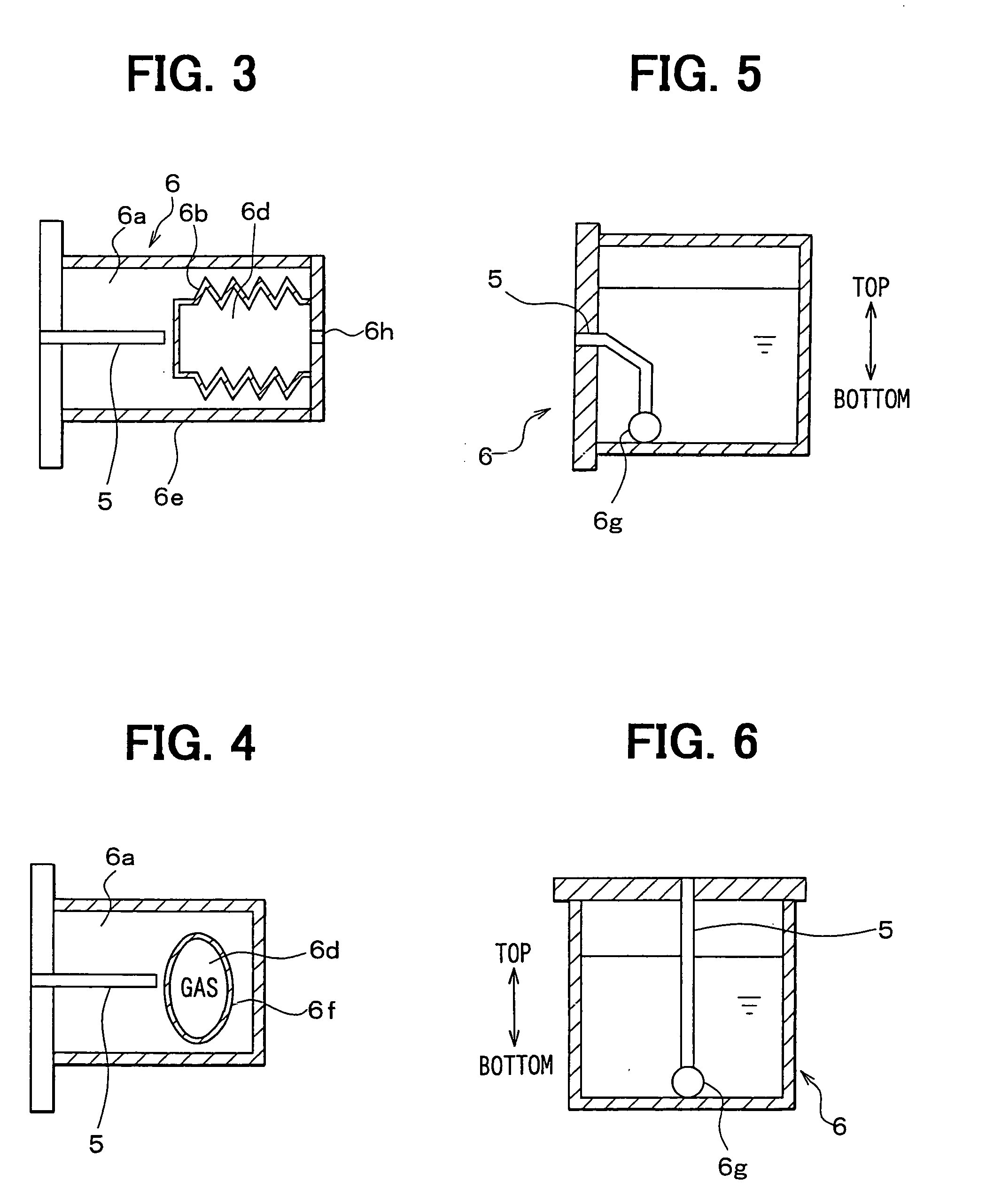
[0077] In the first embodiment, the space in the bellows 6b was employed as the liquid tank chamber 6a. However, as shown in FIG. 3, this embodiment is adapted such that the buffer tank 6 includes a liquid tank chamber 6a filled with a liquid and a gas tank chamber 6d filled with a gas. Also employed is a bellows 6b, which is elastically deformable and displaceable, as a partition for defining the liquid tank chamber 6a and the gas tank chamber 6d.
[0078] In this second embodiment, the space defined by the bellows 6b and a cylindrical housing 6e serves as the liquid tank chamber 6a, while the space in the bellows 6b serves as the gas tank chamber 6d. Since the gas tank chamber 6d is a closed space in this embodiment, a gas to be sealed in the gas tank chamber 6d is preferably an inert gas such as nitrogen. However, to provide a hole 6h for the gas tank chamber 6d to define an open space, the buffer tank 6 is configured substantially in the same manner as in...
third embodiment
[0079] [Third Embodiment]
[0080] This embodiment is a modified example of the second embodiment. More specifically, as shown in FIG. 4, a partitioning member for defining the liquid tank chamber 6a and the gas tank chamber 6d is a thin-film bag-shaped member 6f made of an elastic material such as rubber. In this embodiment, the space defined by the bag-shaped member 6f and the housing 6e serves as the liquid tank chamber 6a, while the closed space in the bag-shaped member 6f serves as the gas tank chamber 6d.
PUM
 Abstract
Description
Claims
Application Information
 - R&D
- Intellectual Property
- Life Sciences
- Materials
- Tech Scout
- Unparalleled Data Quality
- Higher Quality Content
- 60% Fewer Hallucinations
Browse by: Latest US Patents, China's latest patents, Technical Efficacy Thesaurus, Application Domain, Technology Topic, Popular Technical Reports.
© 2025 PatSnap. All rights reserved.Legal|Privacy policy|Modern Slavery Act Transparency Statement|Sitemap|About US| Contact US: help@patsnap.com