
System and process for heat treatment of glass

a technology of heat treatment and glass, applied in the field of systems and processes for heat treatment of glass, can solve problems such as limiting the protection range, and achieve the effect of reducing operating costs and facilitating efficient convection

Inactive Publication Date: 2005-02-03
EDMUND ERDMANN
View PDF20 Cites 1 Cited by
  • Summary
  • Abstract
  • Description
  • Claims
  • Application Information

AI Technical Summary

Benefits of technology

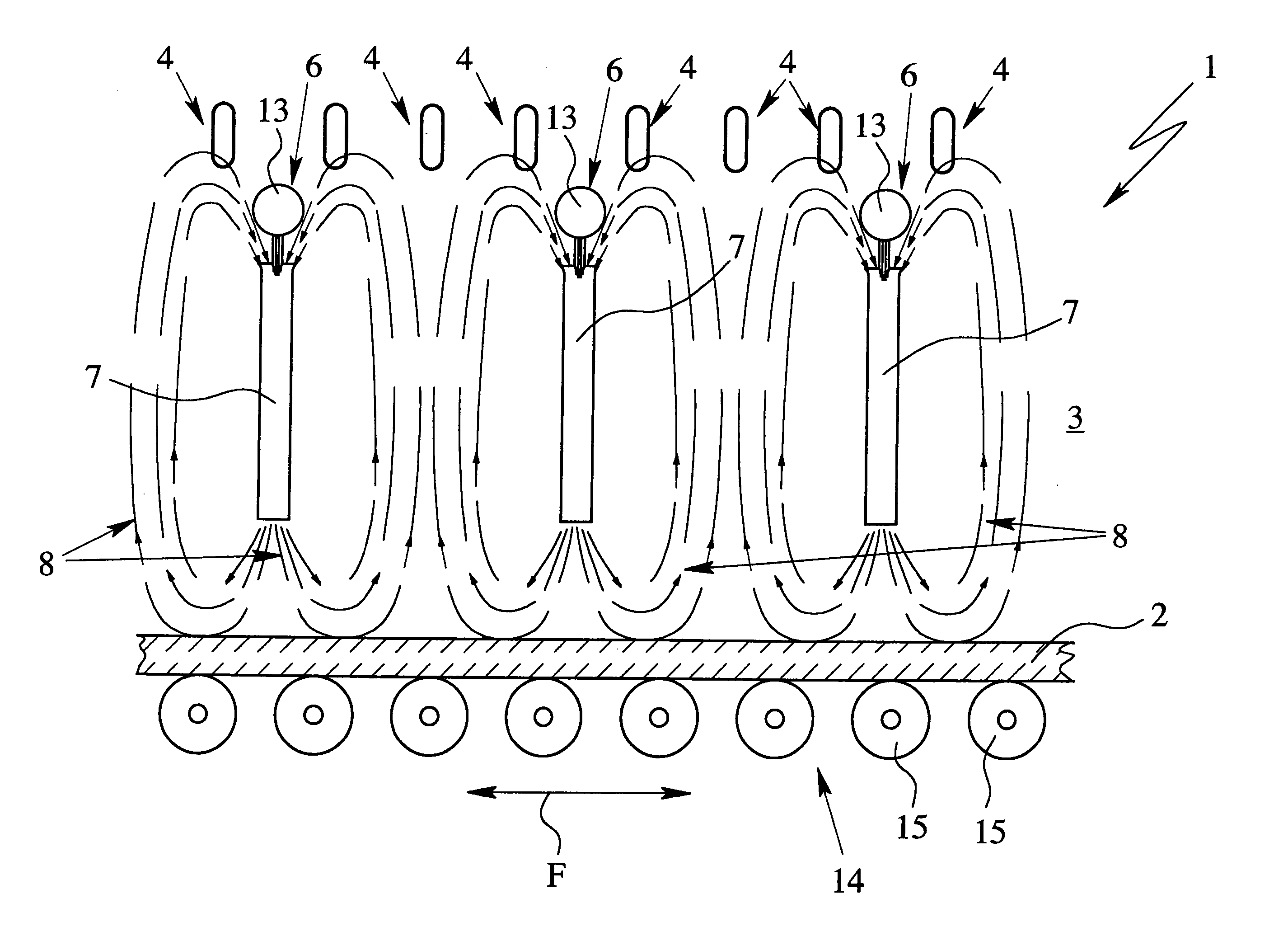
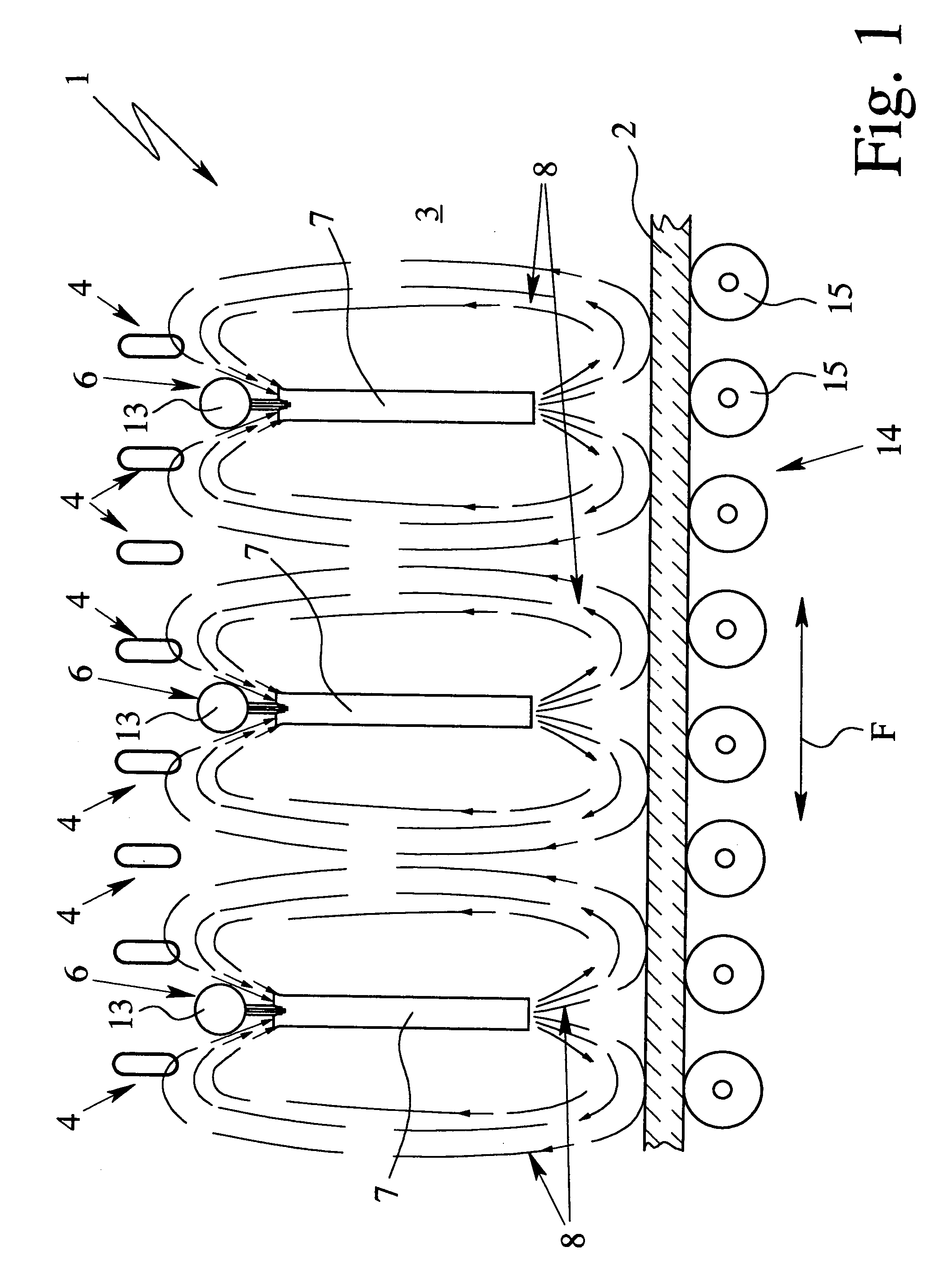
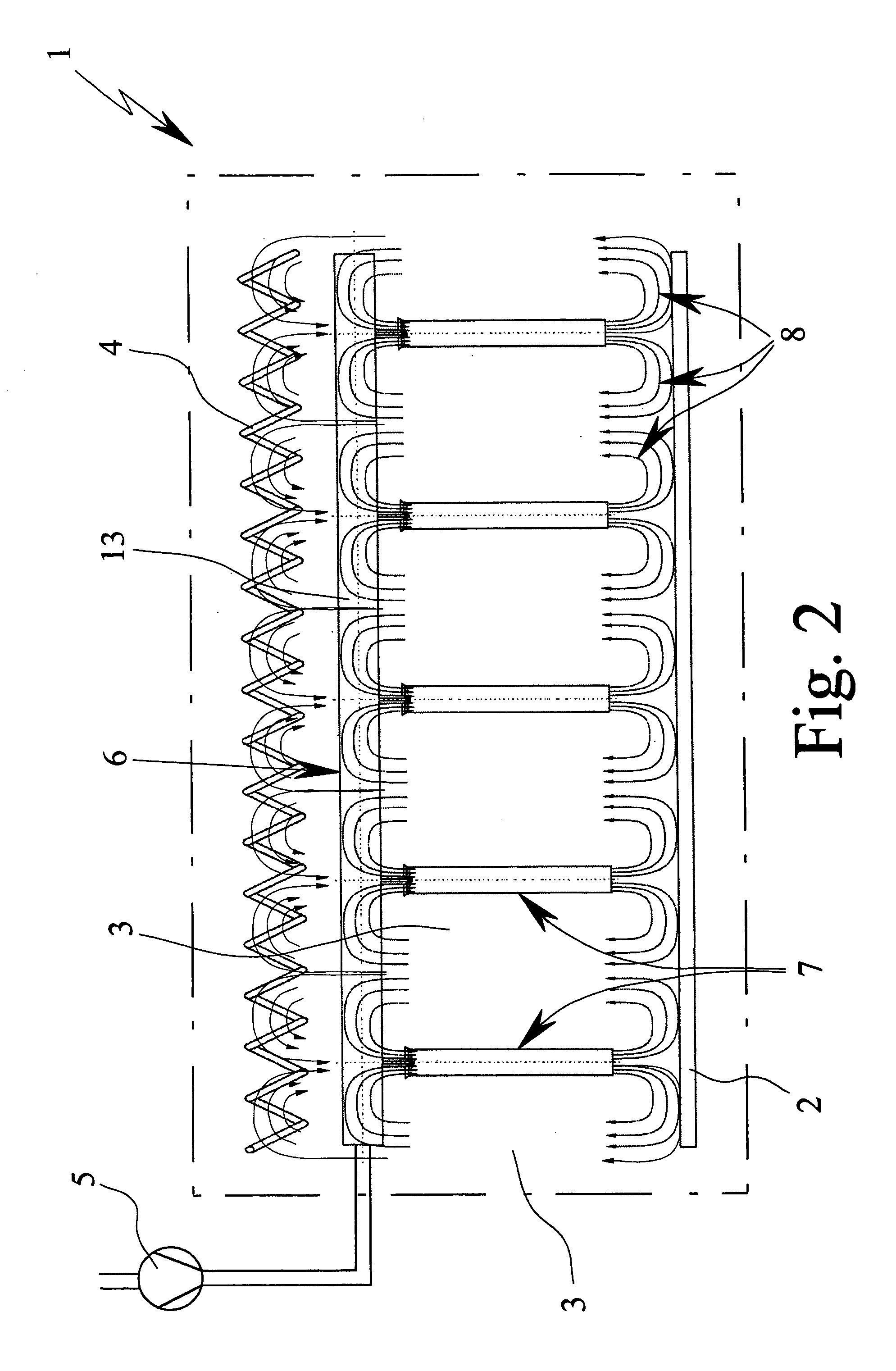
[0013] Another aspect of this invention resides in that each of the propellant air fans has a mixing section with a constant clear diameter or cross section. As a result, efficient convection is provided with distinctly less fan air being required than in the prior art. In particular, it is possible to directly feed the fan air without preheating.
[0015] In fact, in the course of operation, fan air which has not been preheated can be supplied to the propellant air fans. As a result, the system does not have preheating for the fan air and, in fact, need not have it. It has been recognized that the mass flow of fan air which has not been preheated, due to the higher density of the fan air, is higher and thus improved acceleration of the chamber air in the mixing section of the propellant air fan takes place. Against all expectations, the efficiency for convection with the system of the present invention is therefore higher, not lower.
[0017] Another aspect of this invention which can also be implemented independently is that the air swirls produced by the propellant air fan flow around or brush at least one heating means at a time in the heating chamber. This is in turn conducive to efficient convection so that in particular a reduction of the operating costs is enabled.

Problems solved by technology

However, this is not intended to limit the scope of protection.

Method used


Image

  • System and process for heat treatment of glass
  • System and process for heat treatment of glass
  • System and process for heat treatment of glass

Examples


Embodiment Construction

[0023] In the figures, for the same or similar parts, the same reference numbers are used, the corresponding or comparable advantages and properties being achieved even if a repeated description is omitted for reasons of simplification.

[0024] The present invention is directed primarily to the heat treatment of glass. Technically similar problems can also be observed in other materials which are to be treated at high temperatures, so that in principle the teaching of this invention can also relate to systems and processes for heat treatment of other materials which are to be treated with high temperatures, for example, aluminum sheet. Otherwise, it applies that the glass which is to be heat-treated within the scope of the teaching of the invention is normally flat glass, therefore plate glass.

[0025]FIG. 1 shows a schematic lengthwise section of a system 1 of the present invention for heat treatment of glass 2, in extract form. FIG. 2 shows the system 1 in a partial cross section, t...


PUM

PropertyMeasurementUnit
lengthaaaaaaaaaa
diameteraaaaaaaaaa
diameteraaaaaaaaaa

Abstract

A system and a process for heat treatment of glass or other materials where fan air is blown into a heating chamber via propellant air fans and the chamber air is circulated. In order to achieve effective convection, the propellant air fans have cylindrical mixing sections. Additionally, resulting air swirls flow around the heating means which are located in the heating chamber.

Description

BACKGROUND OF THE INVENTION [0001] 1. Field of the Invention [0002] The present invention relates generally to a systems and processes for heat treatment of glass and more specifically to heat treatment of glass in a tempering system. [0003] 2. Description of Related Art [0004] In the heat treatment of glass, especially in a tempering system or tempering furnace, there are conventionally radiant heaters to heat the glass. The heat is injected at least in large part via heat radiation. [0005] In particular, in so-called low-E glass (i.e., glass with low emission, conventionally by a reflective coating) a problem exists where heat injection, which is much less compared to normal glass, is possible by heat radiation. Alternatively or in addition, therefore there is heat transfer by convection (a warm or hot air flow being directed at the glass or routed past it) to improve heat exchange. [0006] A similar problem, especially relevant again with low-E glass, resides in “key formation” as...

Claims


Application Information

Patent Timeline
Patent Type & Authority Applications(United States)
IPC IPC(8): C03B29/08
CPCC03B29/08
Inventor ERDMANN, WOLFGANG
Owner EDMUND ERDMANN
Learn More