
Security architecture for system on chip

Inactive Publication Date: 2005-01-27
IBM CORP
View PDF6 Cites 111 Cited by
  • Summary
  • Abstract
  • Description
  • Claims
  • Application Information

AI Technical Summary

Benefits of technology

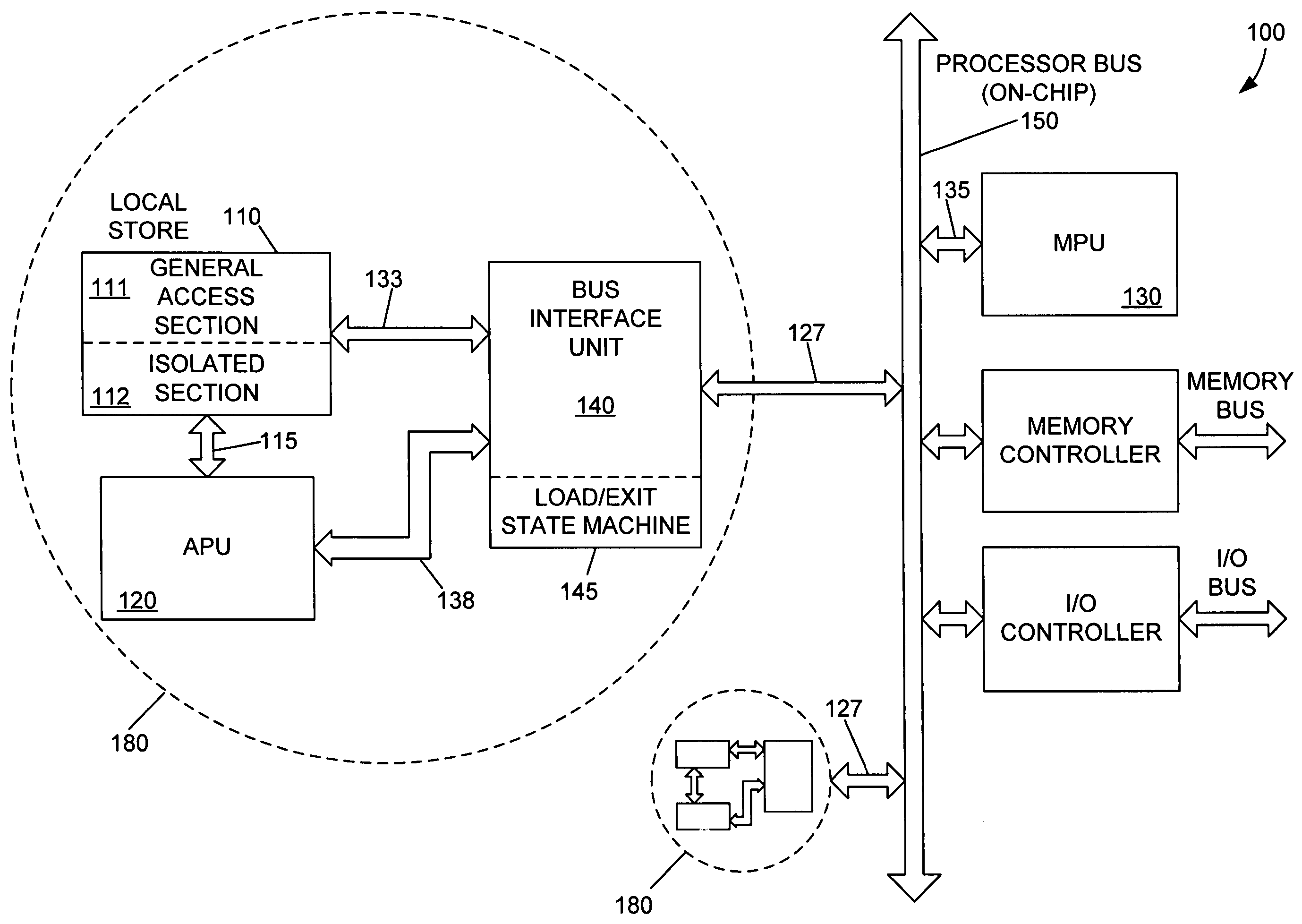
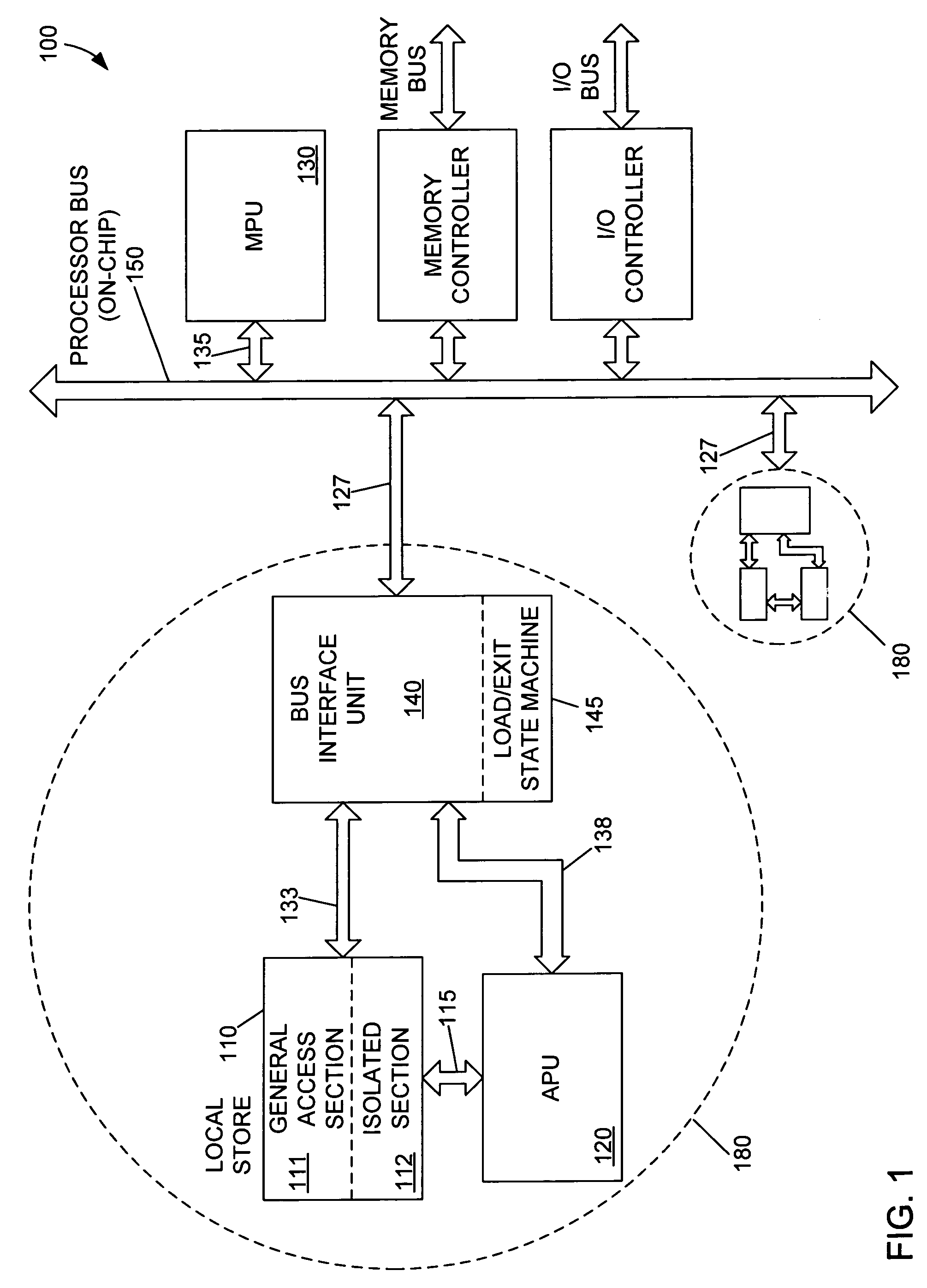
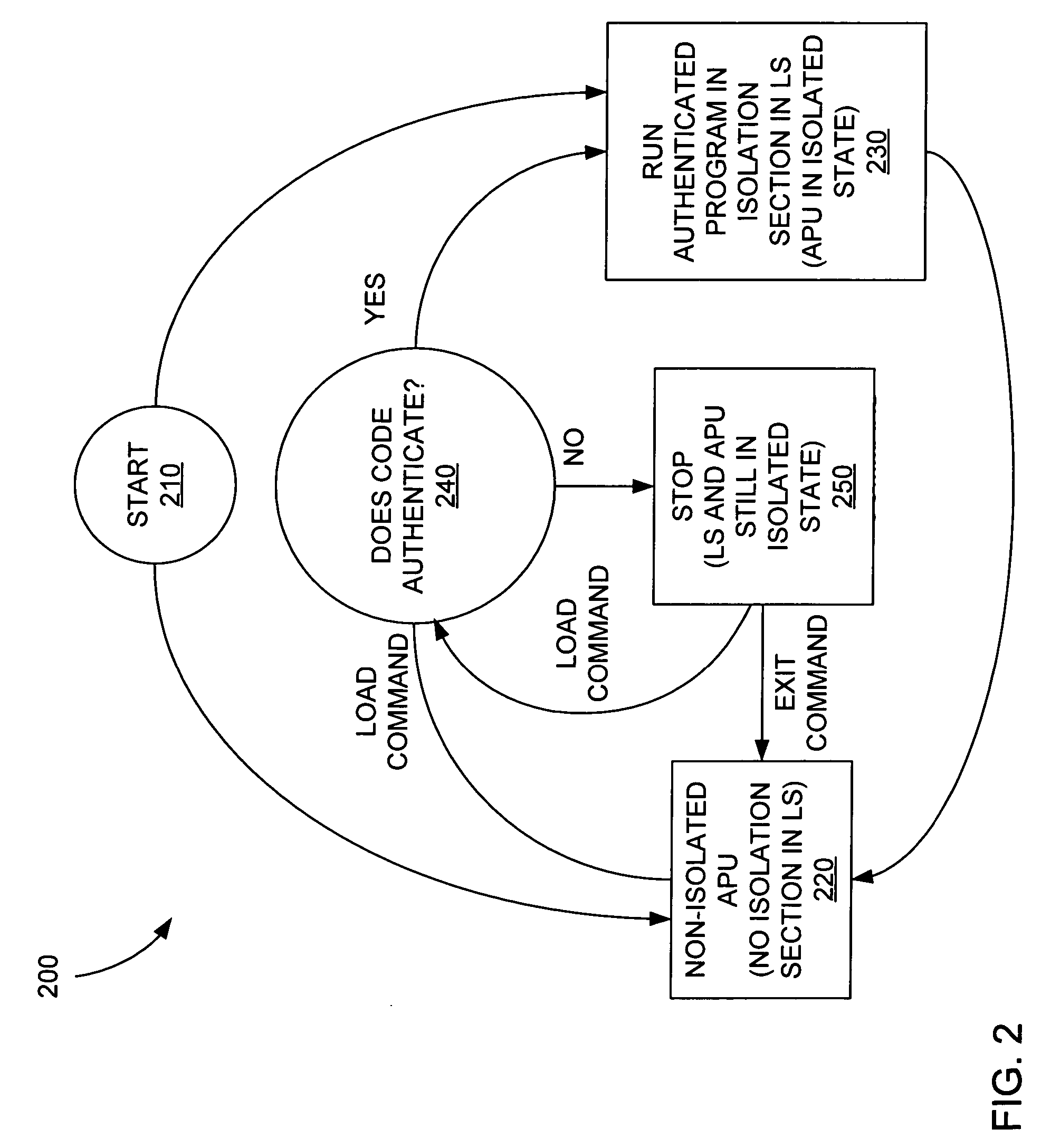
[0009] The present invention provides for dynamically configuring a processor for security functions by partitioning and un-partitioning a local store coupled to a processor for the authentication of code or data. The local store is partitioned into an isolated and non-i

Problems solved by technology

Communications to and from the network can be monitored and, therefore, cannot be trusted.
This lack of security can require authentication and encryption functions to be performed in the constituent networked processors.
Operating systems, however, can be insecure, with some operating systems requiring security fixes at a rate of up to one a week.
These continually discovered security breaches represent windows of opportunity for an unauthorized third party to access code.
This can make it very difficult to mount a software attack on such a chip.
This type of mechanism, for example, therefore does not provide good protection for implementing a secure boot function because the authenticated operating system image can relatively easily be replaced.
Some of the disadvantages of this arrangement, however, are that the unit can occupy a significant silicon area on the processor chip, which is typically implemented in significantly more expensive technology and that such a unit, if it is to be realized at a reasonable cost (area), can provide basic functionality only.
In other words, the unit is not generally programmable, and the array of security functions it can provide is limited.
A third limitation can be that communications on the on-chip bus may be monitored if the operating system is compromised.

Method used


Image

  • Security architecture for system on chip
  • Security architecture for system on chip
  • Security architecture for system on chip

Examples


Embodiment Construction

[0013] In the following discussion, numerous specific details are set forth to provide a thorough understanding of the present invention. However, those skilled in the art will appreciate that the present invention may be practiced without such specific details. In other instances, well-known elements have been illustrated in schematic or block diagram form in order not to obscure the present invention in unnecessary detail. Additionally, for the most part, details concerning network communications, electromagnetic signaling techniques, and the like, have been omitted inasmuch as such details are not considered necessary to obtain a complete understanding of the present invention, and are considered to be within the understanding of persons of ordinary skill in the relevant art.

[0014] In the remainder of this description, a processing unit (PU) can be a sole processor of computations in a device. In such a situation, the PU is typically referred to as an MPU (main processing unit)....


PUM


Abstract

The present invention provides for authenticating code and / or data and providing a protected environment for execution. The present invention provides for dynamically partitioning and un-partitioning a local store for the authentication of code or data. The local store is partitioned into an isolated and non-isolated section. Code or data is loaded into the isolated section. The code or data is authenticated in the isolated section of the local store. After authentication, the code is executed. After execution, the memory within the isolated region of the attached processor unit is erased, and the attached processor unit de-partitions the isolated section within the local store.

Description

TECHNICAL FIELD [0001] The invention relates generally to authenticating code and / or data in a chip and, more particularly, to authenticating and protecting code and / or data within an isolated section of an attached processor unit. BACKGROUND [0002] In modern microprocessors, support of security functions is of increasing importance. One primary reason is that increasingly, processors are networked. Communications to and from the network can be monitored and, therefore, cannot be trusted. This lack of security can require authentication and encryption functions to be performed in the constituent networked processors. [0003] The use of networked computers for business purposes, such as enabling payment systems and so on, requires authentication and protection of data and, in cases where it is distributed over the network, code. Authentication can be generally defined as the determination as to whether code or data has been tampered with or otherwise altered. Hardware and software in ...

Claims


Application Information

Patent Timeline
IPC IPC(8): G06F12/14G06F21/22G06F21/24G09C1/00H04L9/08
CPCG06F21/53H04L2209/56H04L9/3226
Inventor CRAFT, DAVID JOHNDAY, MICHAEL NORMANHOFSTEE, HARM PETERJOHNS, CHARLES RAYLIBERTY, JOHN SAMUEL
Owner IBM CORP
Learn More