
Collision object discrimination apparatus for vehicles

Inactive Publication Date: 2005-01-27
DENSO CORP
View PDF5 Cites 63 Cited by
  • Summary
  • Abstract
  • Description
  • Claims
  • Application Information

AI Technical Summary

Benefits of technology

[0010] It is therefore an object of the present invention to provide a collision object discrimination apparatus for vehicles, which can accurately discriminate collision objects irrespective of the change of rigidities and shapes of collision objects.
[0013] When the collision width is detected, the rigidity of the collision object can be detected using the collision width and the collision load. It is assumed that the rigidity of the collision object means a parameter indicating the resistance of the collision portion to deformation at the time of collision. A pedestrian, that is, a human being and another collision object are considerably different from each other in rigidity. Accordingly, when discrimination of the collision object is made based on the rigidity of the collision object, the collision object having the rigidity different from a pedestrian can be accurately discriminated from a pedestrian.

Problems solved by technology

When a protection apparatus (for example, an active hood) on a vehicle front part is activated in thecase where a collision object is not a pedestrian (human being), various undesirable influences arise.
For example, when discrimination from a pedestrian cannot be made in the case where a collision occurs with a light object such as a construction signboard, the protection apparatus is unnecessarily activated and a repair cost incurs.
Besides, when discrimination from a pedestrian cannot be made in the case where a collision occurs with a heavy fixture such as a concrete wall or a vehicle, the hood moves back in a state where it is raised.
In this instance, the hood enters a vehicle interior and damages a passenger in the vehicle.
Thus, the accurate pedestrian discrimination is difficult when only the above duration time of the collision load, the increasing rate or the peak value is used.

Method used


Image

  • Collision object discrimination apparatus for vehicles
  • Collision object discrimination apparatus for vehicles
  • Collision object discrimination apparatus for vehicles

Examples


first embodiment

[0067] [First Embodiment]

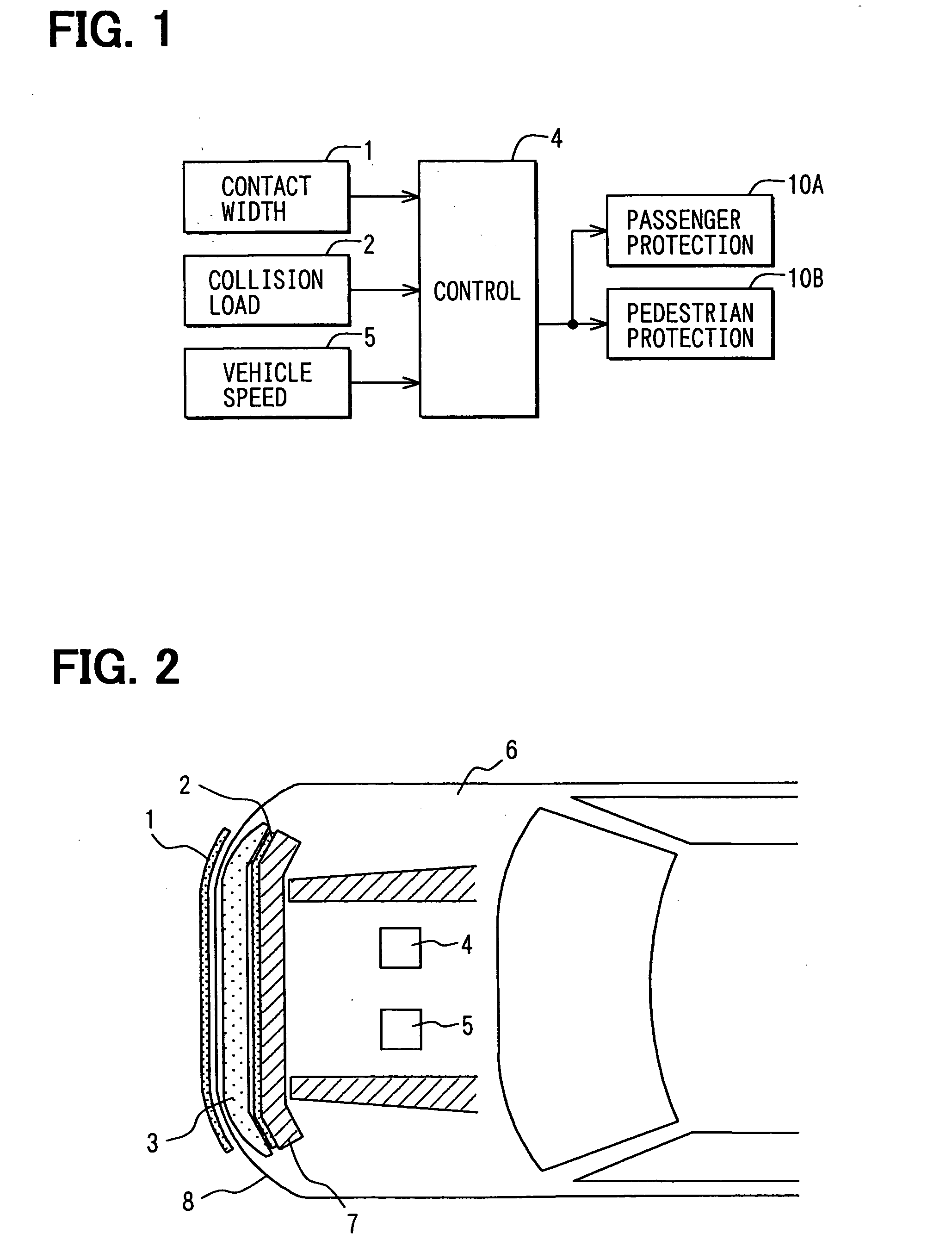
[0068] Referring first to FIG. 1, a collision object determination apparatus according to a first embodiment is comprised a contact width detection sensor 1, a collision load detection sensor 2, an electronic control unit 4 and a vehicle speed sensor 5. The control unit 4 outputs information relating to collision to a passenger protection apparatus 10A and a pedestrian protection apparatus 10B. This information includes information as to whether or not a collision object is a pedestrian.

[0069] The contact width detection sensor 1 is provided as a first collision detection sensor and extends in the lateral direction at the front surface of a bumper cover 8 surrounding a bumper (absorber) 3. The collision load detection sensor 2 is provided as a second collision detection sensor and extends in the lateral direction at the rear surface of the bumper 3. The bumper 3 is provided to extend in the lateral direction at the front surface of a bumper reinforcing memb...

first modification

[0093] (First Modification)

[0094] A modification of a pedestrian discrimination will be described with reference to a flowchart shown in FIG. 10.

[0095] In FIG. 10, the processing till step S21 is the same as that of FIG. 9. In this modification, even in the case where the collision object collision rigidity Kc is within the range where the collision object can be regarded as a pedestrian, it is not immediately determined to be a pedestrian. An additional pedestrian discrimination routine is further carried out to improve a pedestrian discrimination accuracy.

[0096] First, it is determined (S24) whether or not the collision width W falls within a predetermined range of Wth1 to Wthh as a possible range of a pedestrian lateral width. If the collision width does not fall in the predetermined range, the collision object is determined to be other than a pedestrian (S25). If it falls in the predetermined range, a built-in timer T2 is reset (S26) and the collision load F is again read (S27...

second modification

[0101] (Second Modification)

[0102] A further modification of pedestrian discrimination will be described with reference to a flowchart shown in FIG. 11. In this discrimination process, the change of the collision load due to the vehicle speed V is corrected.

[0103] Specifically, after S12, the vehicle speed V is read (S34) from the vehicle speed sensor 5. In order to correct the change of the collision load F changing in accordance with the vehicle speed V, the respective thresholds of FIGS. 9 and 10 are calculated or corrected (S35) by using a stored relation between the vehicle speed V and respective thresholds.

[0104] Besides, when composite collision rigidity K, bumper collision rigidity Kb, and collision object mass M are calculated (S36, S37, S38) on the further basis of the vehicle speed V. For this purpose, each map data may be provided for different vehicle speeds. By doing so, the influence of the vehicle speed on the collision load can be compensated.


PUM


Abstract

A collision object discrimination apparatus for vehicles includes two collision detection sensors for discriminating kinds of a collision object based on two sensor outputs. The collision object is determined based on a collision width (W) detected by a collision width detection sensor fitted to a vehicle body. Alternatively, the collision object is determined based on a difference between operation characteristics of the two sensors. Further alternatively, the two sensors are integrated into a single unit including a plurality of censor cells.

Description

CROSS REFERENCE TO RELATED APPLICATION [0001] This application is based on and incorporates herein by reference Japanese Patent Applications No. 2003-279257 filed Jul. 24, 2003 and No. 2004-173056 filed Jun. 10, 2004. FIELD OF THE INVENTION [0002] The present invention relates to a collision object discrimination apparatus for vehicles which discriminates an object colliding against a vehicle. BACKGROUND OF THE INVENTION [0003] When a protection apparatus (for example, an active hood) on a vehicle front part is activated in thecase where a collision object is not a pedestrian (human being), various undesirable influences arise. For example, when discrimination from a pedestrian cannot be made in the case where a collision occurs with a light object such as a construction signboard, the protection apparatus is unnecessarily activated and a repair cost incurs. [0004] Besides, when discrimination from a pedestrian cannot be made in the case where a collision occurs with a heavy fixture...

Claims


Application Information

Patent Timeline
IPC IPC(8): G01P15/00B60R21/00B60R21/01B60R21/34G01L1/20G01P15/12G06F17/00
CPCB60R21/34B60R21/0136
Inventor TAKAFUJI, TETSUYAHATTORI, YOSHIYUKIKIRIBAYASHI, SHINICHI
Owner DENSO CORP
Learn More