
Polyolefin microporous membrane and method of evaluating the same

a polyolefin and microporous membrane technology, applied in the direction of membranes, cell components, cell component details, etc., can solve the problems of inner electrical short, inner electrical short, shrinking and going inside the electrode,

Active Publication Date: 2005-01-27
ASAHI KASEI CHEM CORP
View PDF3 Cites 30 Cited by
  • Summary
  • Abstract
  • Description
  • Claims
  • Application Information

AI Technical Summary

Benefits of technology

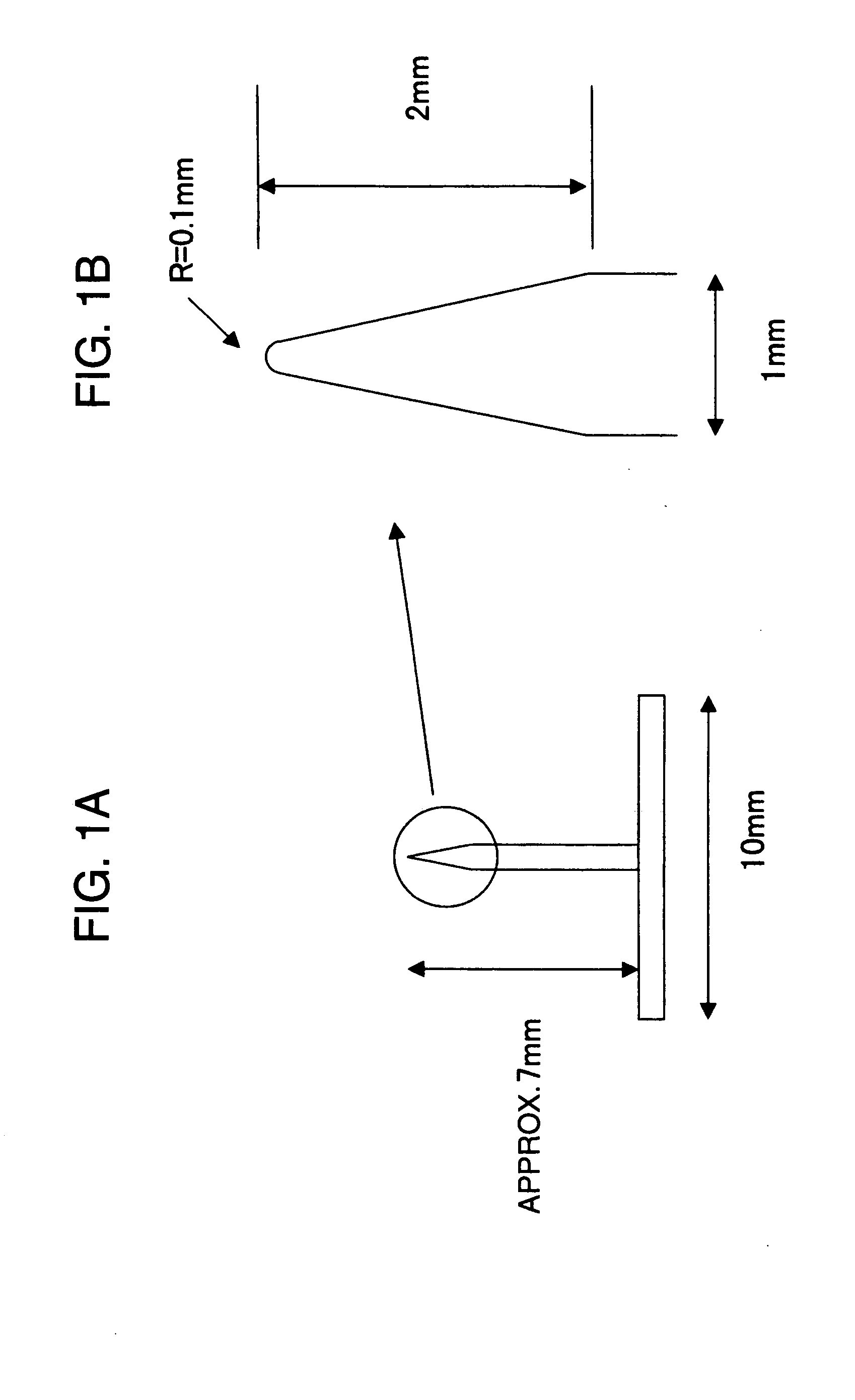
(8) A method for evaluating a heat resistance property of a microporous membrane, comprising: preparing a cell by overspreading a piece of a microporous membrane over a pointed end element having a pointed end like a needle, which is fixed on

Problems solved by technology

On the other hand, when the interior temperature of the battery becomes high, the separator arranged between the electrodes may be ruptured or shrink, so that the electrodes may be contacted with each other, thereby causing an inner electrical short.
However, if the heat shrinking force and the heat shrinking percentage in a vertical direction toward the winding direction of a laminate of electrodes and a separator (in other words, in a transverse direction to the separator) are large, a phenomenon occurs that the separator shrinks and goes inside the electrodes when the interior temperature of the battery becomes high.
As a result, the electrodes are exposed at both ends of plus and minus electrodes to cause an inner electrical short.
The separator becomes susceptible to be broken through by projections, such as electrodes, when exposed to a high temperature, thereby causing the inner electrical short.
Therefore, even when the longitudinal stretching is carried out after the extraction of any plasticizer while keeping the length in the transverse direction constant, closure of the pores upon longitudinal stretching cannot be prevented from occurring.
As a result, a sufficient permeability can hardly be obtained.
Moreover, the piercing strength is low and the break through temperature is low, because of high orientation in the machine direction.
However, the disclosure of the specification thereof is limited only to a membrane, which is high in its porosity and low in its piercing strength.

Method used


Image

  • Polyolefin microporous membrane and method of evaluating the same
  • Polyolefin microporous membrane and method of evaluating the same
  • Polyolefin microporous membrane and method of evaluating the same

Examples


example 1

3 Weight % of ultra high molecular weight polyethylene having an intrinsic viscosity [η] of 11.5 dl / g, 27 wt % of high density polyethylene having an intrinsic viscosity [η] of 2.8 dl / g, 50.6 wt % of dioctyl phthalate (DOP) and 19.4 wt % of pulverized silica were mixed and granulated. Thereafter, the granulated product was melt-kneaded in a twin screw extruder equipped with a T die at the leading edge, extruded therefrom, and then rolled from both sides with heated rolls, thereby obtaining a sheet like molded product having a thickness of 110 μm. From the molded product, the DOP and pulverized silica were extraction-removed, thereby obtaining a microporous membrane. Two sheets of the microporous membrane were placed one over the other, stretched by 4.5 times in the machine direction at 110° C., thereafter stretched by 1.7 times in the transverse direction at 133° C., and finally heat-treated at 135° C. Physical properties of the thus-obtained microporous membrane are as shown in Ta...

example 2

4.5 Weight % of ultra high molecular weight polyethylene having an intrinsic viscosity [η] of 11.5 dl / g, 25.5 wt % of high density polyethylene having an intrinsic viscosity [η] of 2.8 dl / g, 50.6 wt % of dioctyl phthalate (DOP) and 19.4 wt % of pulverized silica were mixed and granulated. Thereafter, the granulated product was melt-kneaded in a twin screw extruder equipped with a T die at the leading edge, extruded therefrom, and then rolled from both sides with heated rolls, thereby obtaining a sheet like molded product having a thickness of 110 μm. From the molded product, the DOP and pulverized silica were extraction-removed, thereby obtaining a microporous membrane. Two sheets of the microporous membrane were placed one over the other, stretched by 4.5 times in the machine direction at 110° C., thereafter stretched by 1.7 times in the transverse direction at 133° C., and finally heat-treated at 136° C. Physical properties of the thus-obtained microporous membrane are as shown i...

example 3

6 Weight % of ultra high molecular weight polyethylene having an intrinsic viscosity [η] of 11.5 dl / g, 24 wt % of high density polyethylene having an intrinsic viscosity [η] of 2.8 dl / g, 50.6 wt % of dioctyl phthalate (DOP) and 19.4 wt % of pulverized silica were mixed and granulated. Thereafter, the granulated product was melt-kneaded in a twin screw extruder equipped with a T die at the leading edge, extruded therefrom, and then rolled from both sides with heated rolls, thereby obtaining a sheet like molded product having a thickness of 110 μm. From the molded product, the DOP and pulverized silica were extraction-removed, thereby obtaining a microporous membrane. Two sheets of the microporous membrane were placed one over the other, stretched by 4.3 times in the machine direction at 110° C., thereafter stretched by 1.7 times in the transverse direction at 133° C., and finally heat-treated at 137° C. Physical properties of the thus-obtained microporous membrane are as shown in Ta...


PUM

PropertyMeasurementUnit
Temperatureaaaaaaaaaa

Abstract

The invention relates to a microporous membrane, which is provided with high safety even under a condition that the interior temperature of a battery becomes high, and which has high permeability and high mechanical strength at the same time. The polyolefin microporous membrane is characterized by a membrane thickness of 5 to 50 μm, a void content of 30 to 60%, a gas transmission rate of 40 to 300 sec / 100 cc / 20 μm, a piercing strength of not less than 2.5 N / 20 μm and a break through temperature of not lower than 110° C. The separator in accordance with the present invention is used to exhibit high safety under a high temperature condition as well as high permeability, and therefore it is particularly useful as a separator for miniaturized high capacity batteries of a non-aqueous electrolytic solution type.

Description

TECHNICAL FIELD The present invention relates to a microporous membrane made of polyolefin having low gas transmission, superior permeability and superior strength and safety attributes. In particular, the present invention relates to a microporous membrane made of polyolefin which is useful as a separator used for high capacity-carrying lithium ion secondary batteries. BACKGROUND ART Microporous membranes made of polyolefin, such as polyethylene and polypropylene, have been used as separators for batteries such as lithium ion secondary batteries, wherein non-aqueous electrolytic solutions are used. Such a polyolefin separator is known to have high chemical resistance and moreover shutdown function, by which the micropores are blocked up at a temperature close to the melting point of a material due to melting thereof. Therefore, the separator can also play the role of a safety element that, when an abnormal reaction occurs in a battery to raise the battery temperature, terminates ...

Claims


Application Information

Patent Timeline
IPC IPC(8): B01D65/10B01D67/00B01D69/02B01D71/26C08J9/26H01M50/403H01M50/406H01M50/417H01M50/489H01M50/491
CPCB01D65/102B01D67/003B01D69/02B01D71/26C08J9/26C08J2323/00B01D67/0027H01M2/1653H01M2300/0017B01D2323/06B01D2325/04B01D2325/20H01M2/145Y10T428/249953Y02E60/10H01M50/403H01M50/417H01M50/491H01M50/489H01M50/406C08J5/2231C08J9/00B01D71/262B01D71/261
Inventor ADACHI, MASAYUKIIKEMOTO, TAKASHISOGO, HIROSHI
Owner ASAHI KASEI CHEM CORP
Learn More