
Barrier materials and containers made therefrom

a technology of barrier materials and containers, applied in the field of electromagnetic radiation barrier materials, can solve the problems of little or no mechanical protection of payloads, only partially effective foam and masticated paper insulating layers, etc., and achieve the effects of preventing melting or shrinking of payloads, prolonging the shelf life of payloads, and reducing the growth of bacteria

Inactive Publication Date: 2005-01-27
PIEMONTE ROBERT B +2
View PDF32 Cites 5 Cited by
  • Summary
  • Abstract
  • Description
  • Claims
  • Application Information

AI Technical Summary

Benefits of technology

[0008] What are desired are barrier materials, packaging materials and packages made therefrom that maintain the freshness of a payload protected thereby or carried therein, extends the shelf life of the payload, reduces growth of bacteria, retards decay or decomposition of the payload, prevents melting or shrinking of payloads susceptible to such, and maintains the flavor and / or aroma of certain payloads. Barrier materials and packaging made therefrom according to various aspects of the invention may provide one or more of these advantages, or other advantages as will be apparent to the skilled artisan upon reading the following Summary of Invention, as well as reading the following Detailed Description together with the Drawings.

Problems solved by technology

The foam and masticated paper insulating layers are only partially effective due to excessive conduction of heat energy and due to absorption of moisture.
Moreover, they provide little or no mechanical protection for the payload due to their density.

Method used


Image

  • Barrier materials and containers made therefrom
  • Barrier materials and containers made therefrom
  • Barrier materials and containers made therefrom

Examples


Embodiment Construction

[0018] This invention is not limited in its application to the details of construction and the arrangement of components set forth in the following description or illustrated in the drawings. The invention is capable of other embodiments and of being practiced or of being carried out in various ways. Also, the phraseology and terminology used herein is for the purpose of description and should not be regarded as limiting. The use of “including,”“comprising,” or “having,”“containing”, “involving”, and variations thereof herein, is meant to encompass the items listed thereafter and equivalents thereof as well as additional items.

[0019] Aspects of embodiments of the present invention provide a low cost, effective, light-weight structure for protecting and / or insulating a payload, particularly for thermally insulating temperature sensitive payloads for an extended period of time. Comparisons under matched conditions of conventional shipping containers and containers according to aspect...


PUM

PropertyMeasurementUnit
reflectivityaaaaaaaaaa
structureaaaaaaaaaa
transmissionaaaaaaaaaa

Abstract

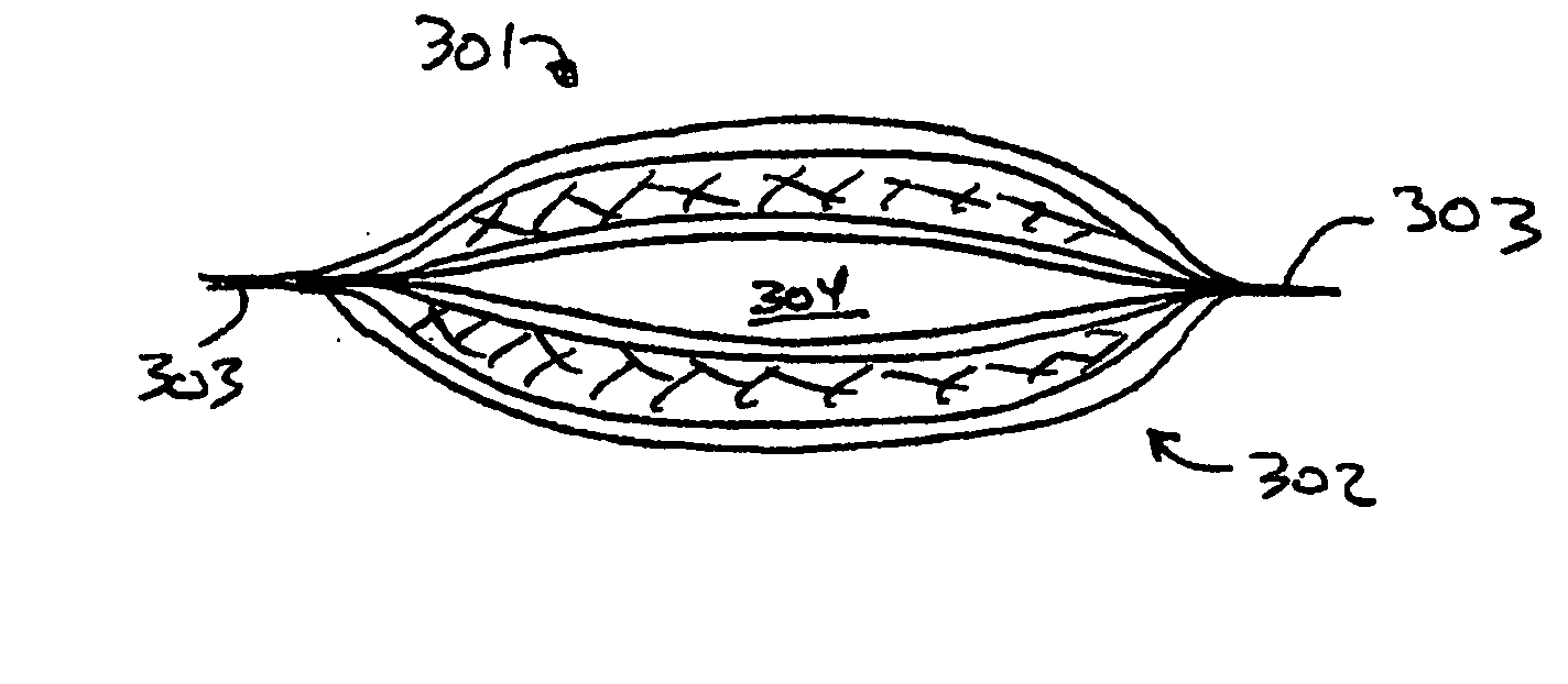
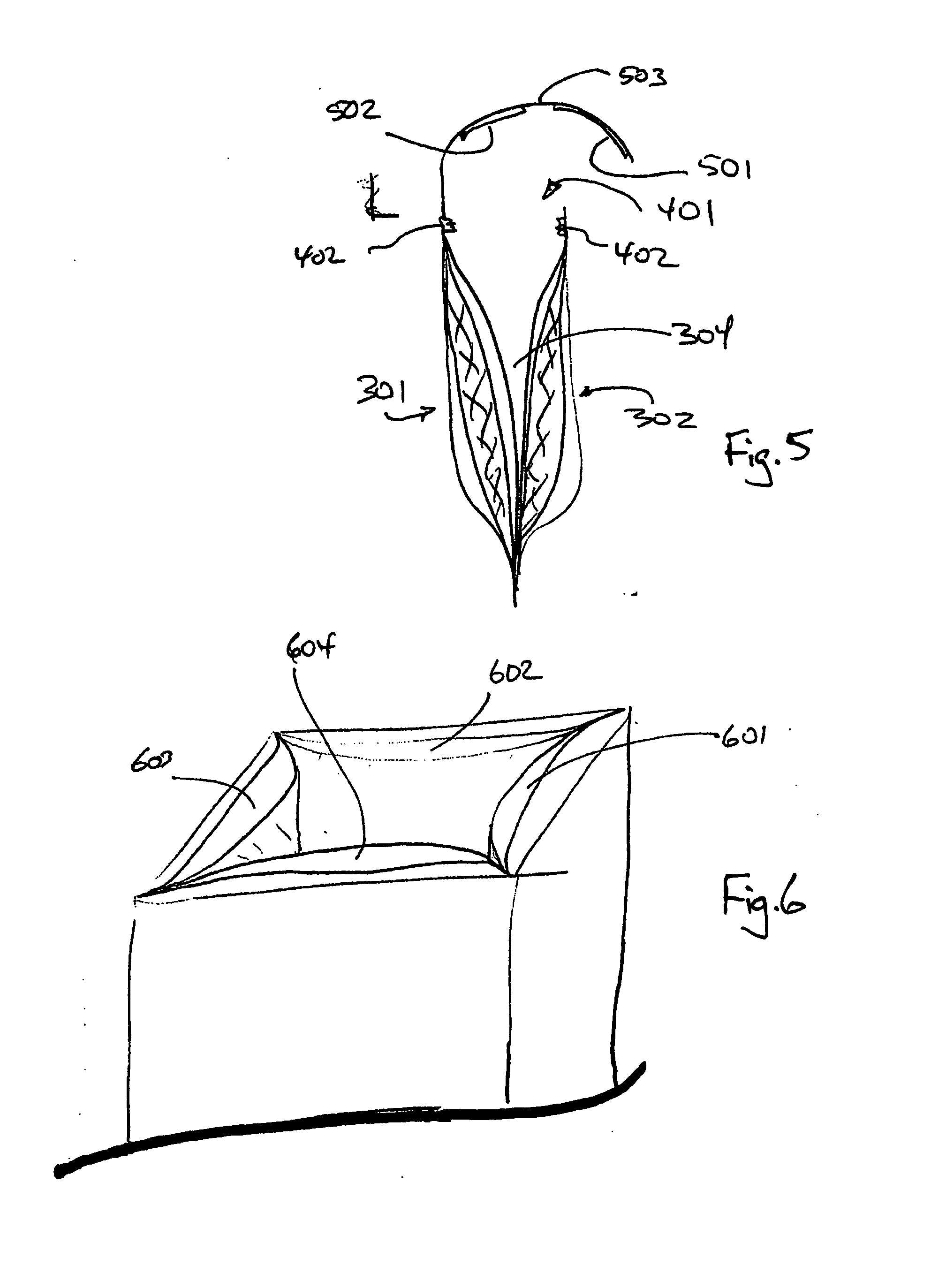
A barrier structure comprises: a first membrane substantially reflective of electromagnetic radiation; a second membrane spaced apart from the first membrane and bound to the first membrane about an edge thereof to form a bladder, the second membrane resistant to vapor transmission; and a fibrous insert disposed between the first membrane and the second membrane so as to maintain the spaced apart relationship, the fibrous insert defining a space holding an insulating medium resistant to the transmission of thermal energy and interspersed therethough. The first membrane may further comprise a multilayer composite and may include a polymer resistant to vapor transmission, for example including at least one of H2O, CO2 and O2. The polymer may be a polyester. The multilayer composite may further comprise a structure substantially reflective of thermal energy. The composite may further comprise one or both of an outer metallization layer and an inner metallization layer. The composite may further comprise a sealing member. The sealing member may be a polyethylene layer. The fibrous insert may comprise randomly oriented fibers of plural deniers bonded together in a crush-resistant structure. The plural deniers may be within a range of 3 to 100 denier. The fibrous insert may further comprise an acrylic binder, an EVCL binder, a polyvinyl acetate (PVA) binder or other polymer binder and combinations thereof. The EVCL binder may be included in the fibrous insert as a percentage of material comprising the fibrous insert of about 35-75% w / w. The first membrane, the second membrane and the fibrous insert may all possess substantially similar melt flow indices. Also shown, a shipping container may comprise plural wall structures according to the thermal barrier structure described, disposed on at least two sides of a payload region, such as a box or envelope. The plural wall structures may be bonded together along at least one edge, for example to form a shipping envelope having an interior payload region surrounded by the bladders of the plural wall structures. The plural structures may further comprise a third membrane resistant to vapor transmission; and another fibrous insert disposed between the second membrane and the third membrane.

Description

RELATED APPLICATIONS [0001] This application claims priority under 35 U.S.C. § 119(e) to U.S. Provisional Application Ser. No. 60 / 482,415, entitled “THERMAL INSULATION CONTAINER,” filed on Jun. 25, 2003, which is herein incorporated by reference in its entirety.BACKGROUND [0002] The present invention relates to electromagnetic radiation barrier materials, particularly thermal barrier insulation materials, especially including thermal barrier insulation materials incorporated in or formed into shipping containers, including envelopes, bags, boxes, cases and the like. [0003] Insulating packaging and materials, especially thermally insulating packaging and materials find many uses in storing and transporting sensitive payloads. Sensitive payloads may include pharmaceuticals, medical products such as blood products, food products and others that are preferably stored and shipped at temperatures below the usual ambient temperature. [0004] An example of the use of thermally insulating mat...

Claims


Application Information

Patent Timeline
Patent Type & Authority Applications(United States)
IPC IPC(8): B32B1/08B65DB65D6/00B65D8/00B65D13/00F16L1/00
CPCB32B3/02B32B27/02B32B27/04B32B27/12B32B27/16Y10T428/13B32B27/30B32B27/32B32B27/36B65D81/3825B65D81/3897B32B27/28
Inventor PIEMONTE, ROBERT B.COX, RICHARD C.HOLICKER, JAMES S.
Owner PIEMONTE ROBERT B
Learn More