
U-shaped locking anti-theft tool storage and support structure in vehicle

a technology of anti-theft tools and support structures, which is applied in the direction of roofs, anti-theft cycle devices, cycle equipments, etc., can solve the problems of limited design freedom below and between both seat rails, and achieve the effect of enhancing the design freedom below and between seat rails

Inactive Publication Date: 2005-01-27
HONDA MOTOR CO LTD
View PDF2 Cites 18 Cited by
  • Summary
  • Abstract
  • Description
  • Claims
  • Application Information

AI Technical Summary

Benefits of technology

[0008] The present invention is made in view of the problems with the known motorcycle anti-theft tool housings, and it is an object of the present invention to provide a housing support structure for a U-shaped locking anti-theft tool in a vehicle, in which a degree of freedom in design below and between both seat rails is enhanced.
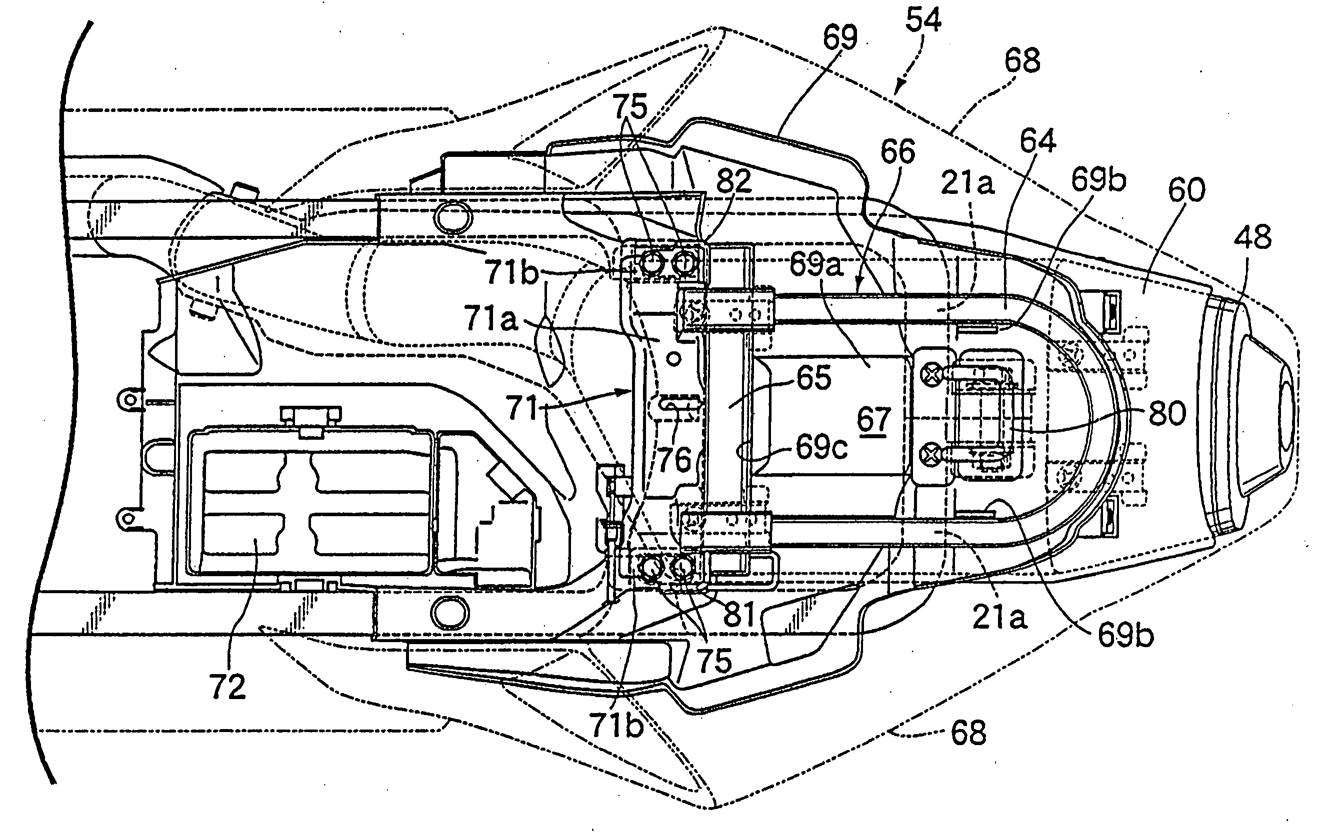
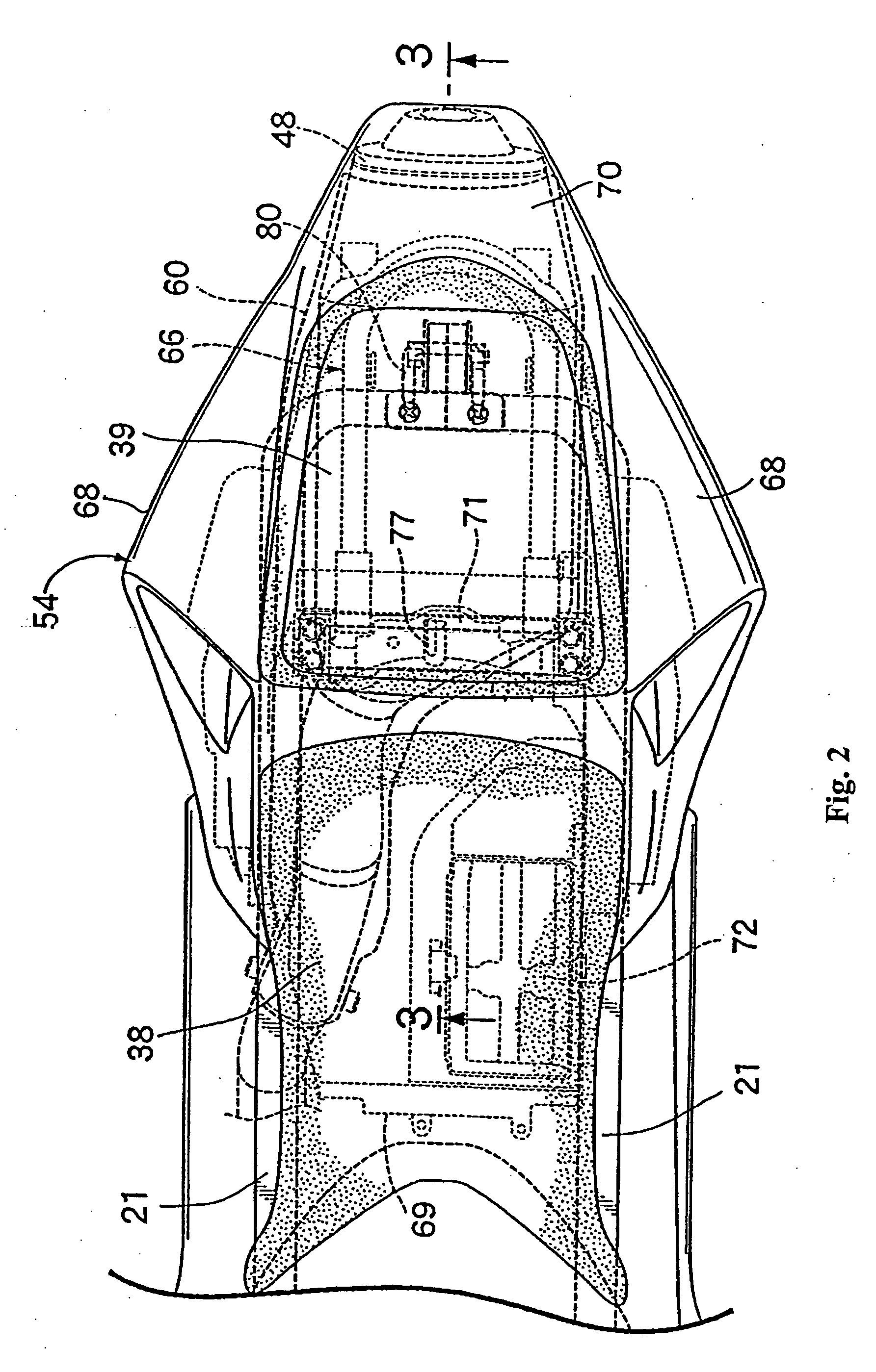
[0011] According to the above-mentioned configuration of the invention according to the first aspect, as the U-shaped locking anti-theft tool is supportively received in the housing inside the rear cover apparatus, with the bottom panel section covering the tops of a pair of seat rails, so that the bottom panel section functions as the bottom of the housing, a degree of freedom in design below and between both seat rails can be enhanced. In addition, as the main bar of the U-shaped locking anti-theft tool is fitted to the cross plate interconnecting the projection bosses of both seat rails in the housing, the supporting rigidity of the U-shaped locking anti-theft tool can also be enhanced.
[0014] Both ends of the main bar of the U-shaped locking anti-theft tool rest on the respective recessed flanking parts. According to such configuration, the rigidity of the cross plate can be enhanced by forming the cross plate in a curved shape, and both ends of the main bar can be stably supported by the cross plate, effectively using the curved shape thereof.

Problems solved by technology

In the above-mentioned conventional structure, although supporting rigidity is enhanced, and the U-shaped locking anti-theft tool can be supported in the housing, a degree of freedom in design below and between both seat rails is limited, because a part of both seat rails is housed in the housing.

Method used


Image

  • U-shaped locking anti-theft tool storage and support structure in vehicle
  • U-shaped locking anti-theft tool storage and support structure in vehicle
  • U-shaped locking anti-theft tool storage and support structure in vehicle

Examples


Embodiment Construction

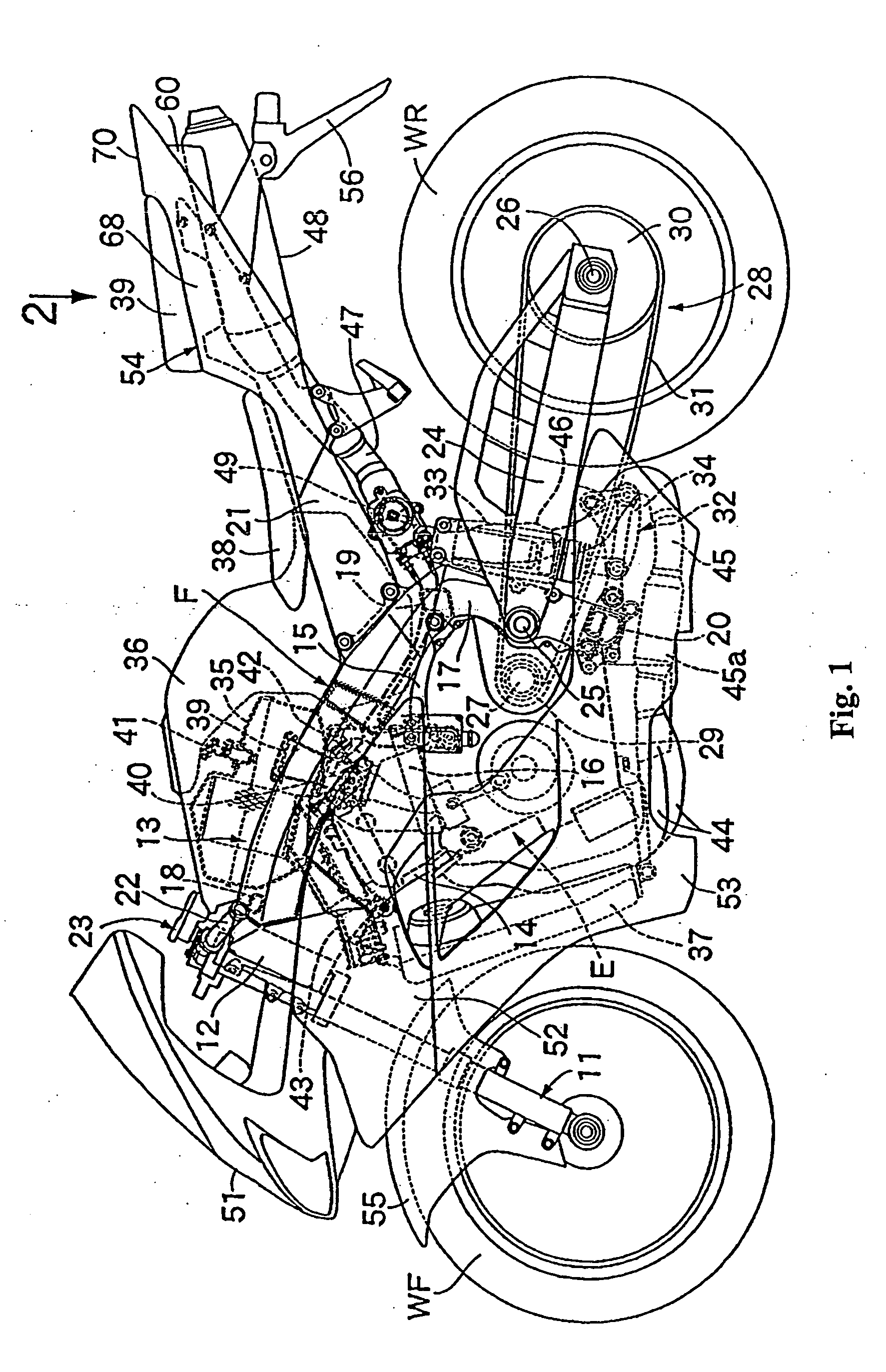
[0023] Referring to the attached drawings, FIGS. 1 to 7 show different aspects of a motorcycle incorporating a selected illustrative embodiment of the present invention.

[0024] As shown in FIG. 1, motorcycle includes a body frame F including a head pipe 12 that supports a front fork 11, which in turn supports a front wheel WF thereon. The head pipe 12 pivotally supports the front fork 11, so that the front fork can be steered.

[0025] The frame F also includes a pair of right and left main frame sections 13, integrally attached to the head pipe 12 and extending rearwardly and downwardly therefrom. The frame F further includes a pair of right and left engine hangers 14, respectively welded to the head pipe 12 and to the front of both main frame sections 13, and extending downwardly from the main frame sections 13. The frame F also includes coupling pipes 16, for coupling each lower part of both engine hangers 14, and supporting plates 15, respectively provided on the rear of each of t...


PUM


Abstract

A housing support structure includes a tool housing for receiving and supporting a U-shaped locking anti-theft tool, in a vehicle having a main frame section and a pair of seat rails. The housing support structure includes a rear cover apparatus having right and left side covers for covering both seat rails from the outside, and a bottom panel section forming the bottom of the housing. The bottom panel section extends between both side covers and is provided for covering both seat rails from the top. The housing is configured to fit on top of the seat rails, with a major part of the seat rails disposed outside of the housing.

Description

CROSS-REFERENCE TO RELATED APPLICATIONS [0001] The present invention claims priority under 35 USC 119 based on Japanese patent application No. 2003-164190, filed Jun. 9, 2003. BACKGROUND OF THE INVENTION [0002] 1. Field of the Invention [0003] The present invention relates to a housing support structure for receiving and storing a U-shaped locking anti-theft tool on a vehicle having right and left seat rails, and a seat supported on the rails, in which the housing is formed inside a rear cover apparatus which covers the outside of both seat rails. More particularly, the present invention relates to the improvement of structure for housing and supporting a U-shaped locking anti-theft tool on a saddle-type vehicle, such as a motorcycle. [0004] 2. Description of the Background Art [0005] A type of tool housing is known for a motorcycle, in which the housing is formed inside a rear cover apparatus which is disposed above the rear wheel of the motorcycle. This known housing covers the ou...

Claims


Application Information

Patent Timeline
Patent Type & Authority Applications(United States)
IPC IPC(8): B62H5/16B62H5/00B62J1/12B62K11/04
CPCB62H5/00B62K11/04B62J1/12B62H2005/008
Inventor NAGASHII, TOSHIHISA
Owner HONDA MOTOR CO LTD
Learn More