
Electrostatic atomizer and method of producing atomized fluid sprays

a technology of atomizer and atomizer, which is applied in the field of atomizer, can solve the problems of unburned hydrocarbon emissions, the formation of deposits in the engine, and the limited combustion process,

Inactive Publication Date: 2005-01-27
MILROST +1
View PDF19 Cites 10 Cited by
  • Summary
  • Abstract
  • Description
  • Claims
  • Application Information

AI Technical Summary

Problems solved by technology

The process of combustion is limited by the size distribution of fuel droplets sprayed into the air stream.
While light fuels like octane have low vapor pressure and evaporate fairly rapidly, heavy hydrocarbons such as diesel and JP8 will take more heat and longer time to completely vaporize in the combustion chamber.
In compression ignition engines, the fine droplets burn too fast, and the larger droplets don't follow the flow path, leading to unburned hydrocarbons emissions or the formation of deposits in the engine.
However, uniform droplet size distribution has been difficult to achieve using conventional high-pressure spray atomizers.
This approach suffers from the drawbacks that (1) uniform droplets are not created and (2) atomization depends on the air velocity, which can vary.
However, the potential payoff for focusing on this mechanism is extremely low.
However, acoustics cannot have direct impact on satellite droplet formation.
Conventional methods of atomizing fluids do not provide the fine control needed to atomize small quantities of fluids efficiently.
This leads to poor results and waste of the fluids.

Method used


Image

  • Electrostatic atomizer and method of producing atomized fluid sprays
  • Electrostatic atomizer and method of producing atomized fluid sprays
  • Electrostatic atomizer and method of producing atomized fluid sprays

Examples


example 1

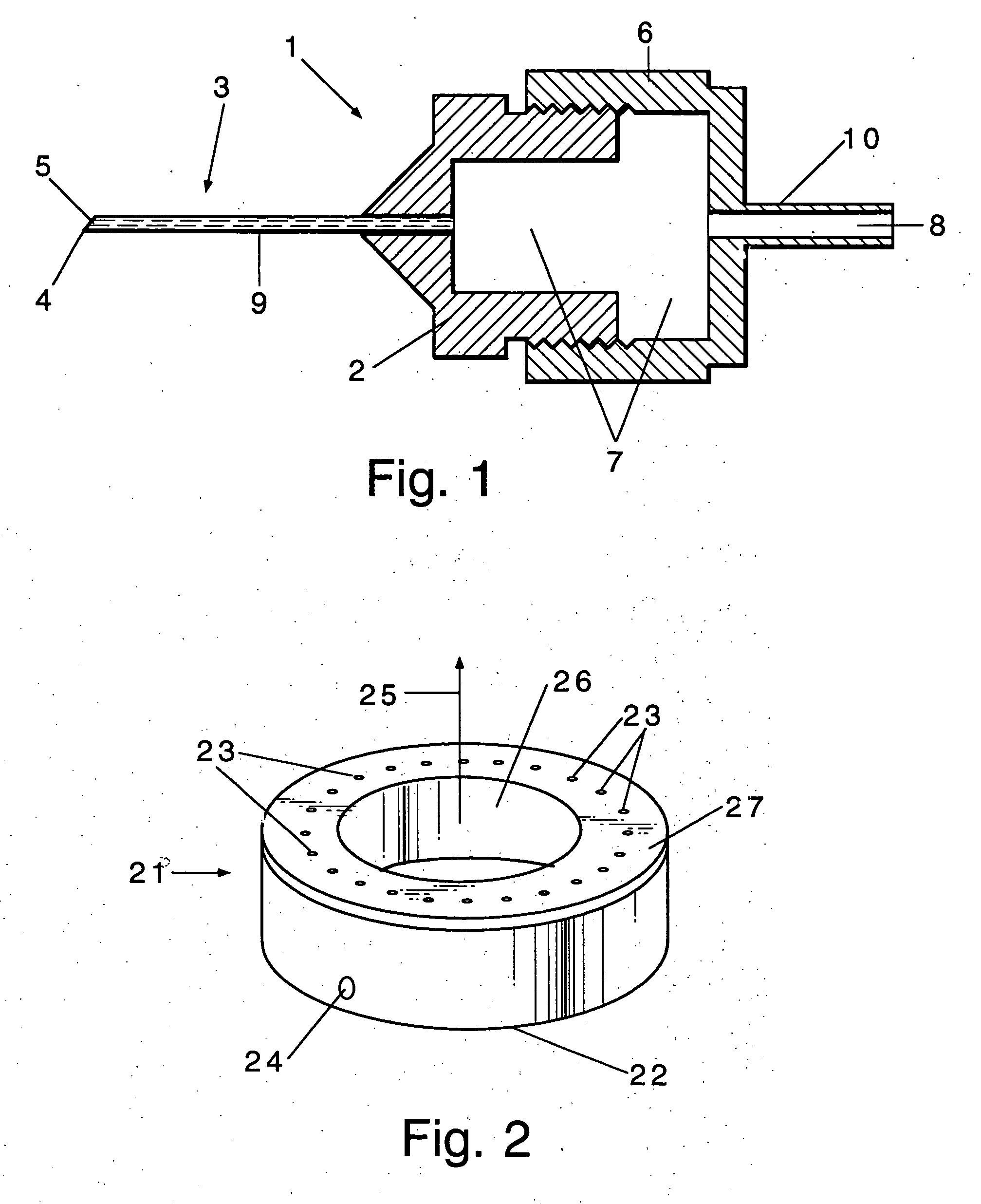
Isopropanol is fed to a 200 μm internal diameter stainless steel hypodermic needle with a pointed tip, with just enough applied hydrodynamic pressure (less than 1 inch water) to maintain a steady stream of fluid to the needle tip. No droplets or mass flow out of the needle is seen until a voltage is applied to the needle. A rectified, 330 Hz, 3-4 kV voltage is supplied to the needle. Droplets (<100 μm diameter) are formed in a single droplet mode. Injection velocity is estimated at 75 mm / s, with slowing due to air drag as the droplets traveled. Power consumption can not be measured because of an extremely low Lissajou current.

example 2

Isopropanol is fed into a 100 μm internal diameter stainless steel needle with a sharp tip, under a pressure equal to approximately 2″ water. An unpulsed DC voltage is applied to the needle. Approximately 4000 volts DC are required to initiate atomization. At about 5000 volts, droplet formation assumes a spray mode with approximately 10 μm / minute mass flow rates. Current consumption at this voltage is about 40 μA. Droplets are very uniform in size and are approximately 30 μm in diameter. Further increasing the DC voltage decreases droplet size and increases mass flow rates, droplet velocity, and dispersion angle.

The applied voltage is then changed to a 100 Hz, 10 kV rectified voltage. A significantly higher mass flow rate, smaller droplet formation and smaller dispersion angle are generated, compared to what is produced with a similar DC voltage. Further, the system can tolerate higher applied hydrodynamic pressures when a pulsed voltage mode of operation is used, as droplet form...

example 3

A mixture of ethanol and less than 0.1 weight percent bacterial spores is prepared. This mixture is atomized using a 620 μm (ID) stainless steel hypodermic needle with a square wave-driven (28 Hz), 20 kV applied voltage and no applied hydrodynamic pressure. Fine droplets in a spray mode are formed.

Similar results are obtained using a 220 μm (ID) needle, or when a 20 kV DC current is applied.

A mixture of water and less than 0.1 weight percent bacterial spores is prepared and atomized using the same 620 μm (ID) stainless steel hypodermic needle with a square wave-driven (28 Hz), 20 kV applied voltage and no applied hydrodynamic pressure. A bimodal spray distribution is observed. The spray assumes a generally conical pattern, with the bacterial spores concentrated in the region near the axis of the cone. Similar results are seen using a 220 μm needle or a 20 kV DC voltage.


PUM


Abstract

Fluids are atomized using a miniaturized electrostatic microinjector. The microinjectors are capable of producing uniform droplets in several spray modes, and metering and dispersing very small volume fluids. The atomizer is useful in carburetion systems for internal combustion engines, to prepare samples for analytical methods such as MALDI, for fluid filtration and separation, and in other applications.

Description

BACKGROUND OF THE INVENTION This invention relates to an atomizer that creates liquid droplets through application of an electrical field. Many processes depend on the formation of liquid droplets of controllable size. Examples of this include internal combustion engines, ink jet and bubble jet printers. Performance of most combustion engines depends strongly on how well the liquid fuel is injected into the combustion chamber or inside the carburetion system. The process of combustion is limited by the size distribution of fuel droplets sprayed into the air stream. The purpose of spray atomization is to create a very small size distribution of droplets with high surface area for heat and mass transfer. Typically, heat and mass transfer scale as d-2 (d is the droplet diameter) while the aerodynamic response time of the droplets scales as d2. Thus, the smaller the droplets, the more rapidly they evaporate while they are given more time for evaporation within the air flow stream. Wh...

Claims


Application Information

Patent Timeline
Patent Type & Authority Applications(United States)
IPC IPC(8): B05B5/00B05B5/025F02M61/02F02M69/04
CPCB05B5/004F02M69/04F02M61/02B05B5/0255
Inventor SHEKARRIZ, ALIREZABIRMINGHAM, JOSEPH G.
Owner MILROST
Learn More