Hydraulic drive system and improved filter sub-system therefor

a technology of filter sub-system and drive system, which is applied in the direction of fluid coupling, hybrid vehicles, couplings, etc., can solve the problems of inability to utilize a conventional filter element, inability to configure and control the drive system, and introduce certain additional requirements and complications into the drive system and controls. , to achieve the effect of reducing flow restriction

Inactive Publication Date: 2005-01-27
EATON CORP
View PDF0 Cites 19 Cited by
  • Summary
  • Abstract
  • Description
  • Claims
  • Application Information

AI Technical Summary

Benefits of technology

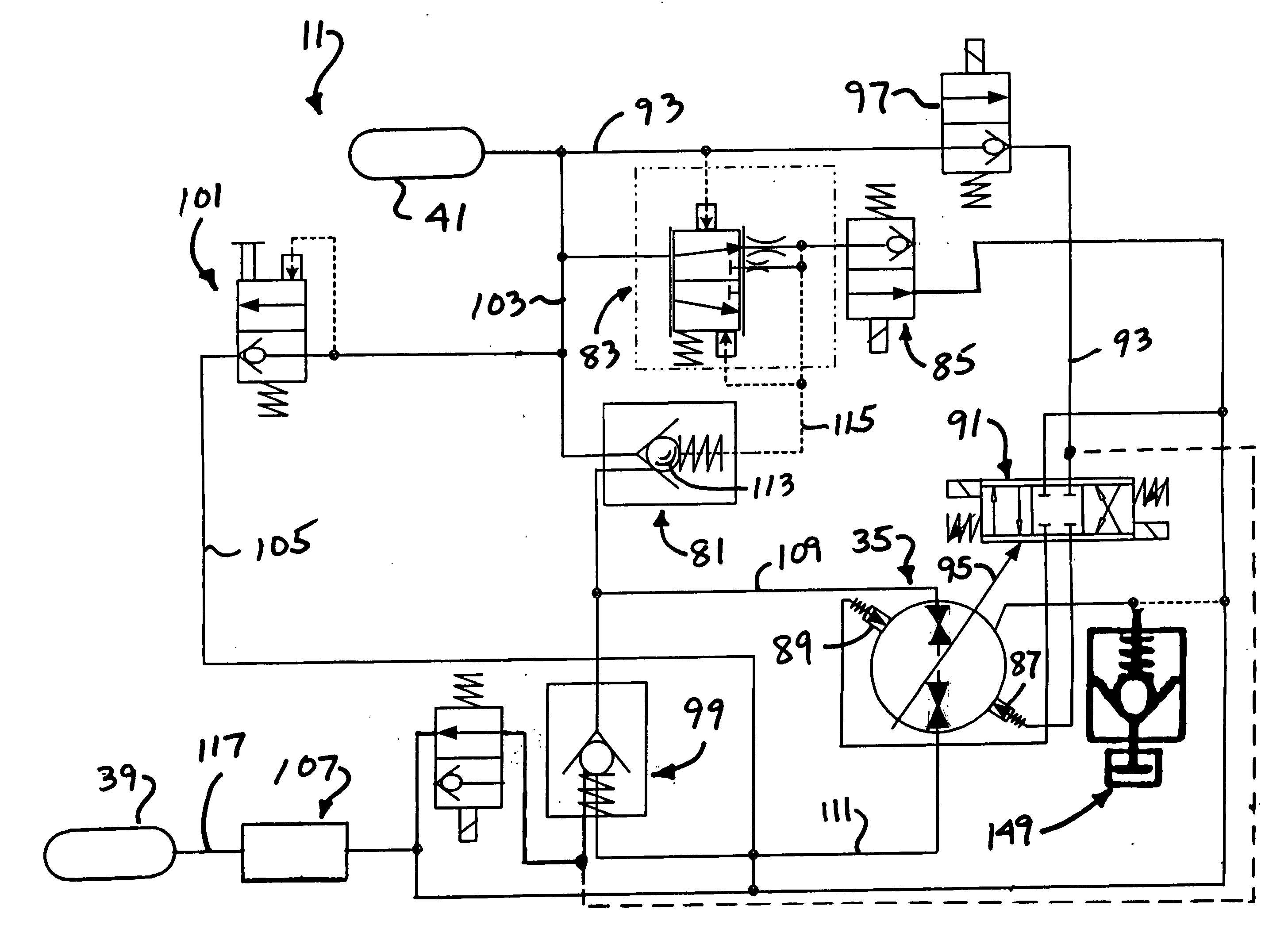
[0008] Accordingly, it is an object of the present invention to provide an improved hydraulic drive system, and a control circuit therefor, of the type which may be utilized in connection with a vehicle hydraulic regenerative braking system, which overcomes the above disadvantages of the prior art.
[0009] It is another object of the present invention to provide such an improved hydraulic drive system which includes a filter sub-system capable of meeting the needs of the system, and of the pump-motor unit, both when the unit is in the pumping mode, and when the unit is in the motoring mode, with no substantial change in system performance as the filter element collects contamination particles.
[0010] It is yet another object of the present invention to provide such an improved filter sub-system which achieves the above-stated objects, and which defines two different flow paths, the first designed to provide relatively little flow restriction when the pump-motor unit is pumping, and the second to accomplish controlled filtration when the unit is motoring.
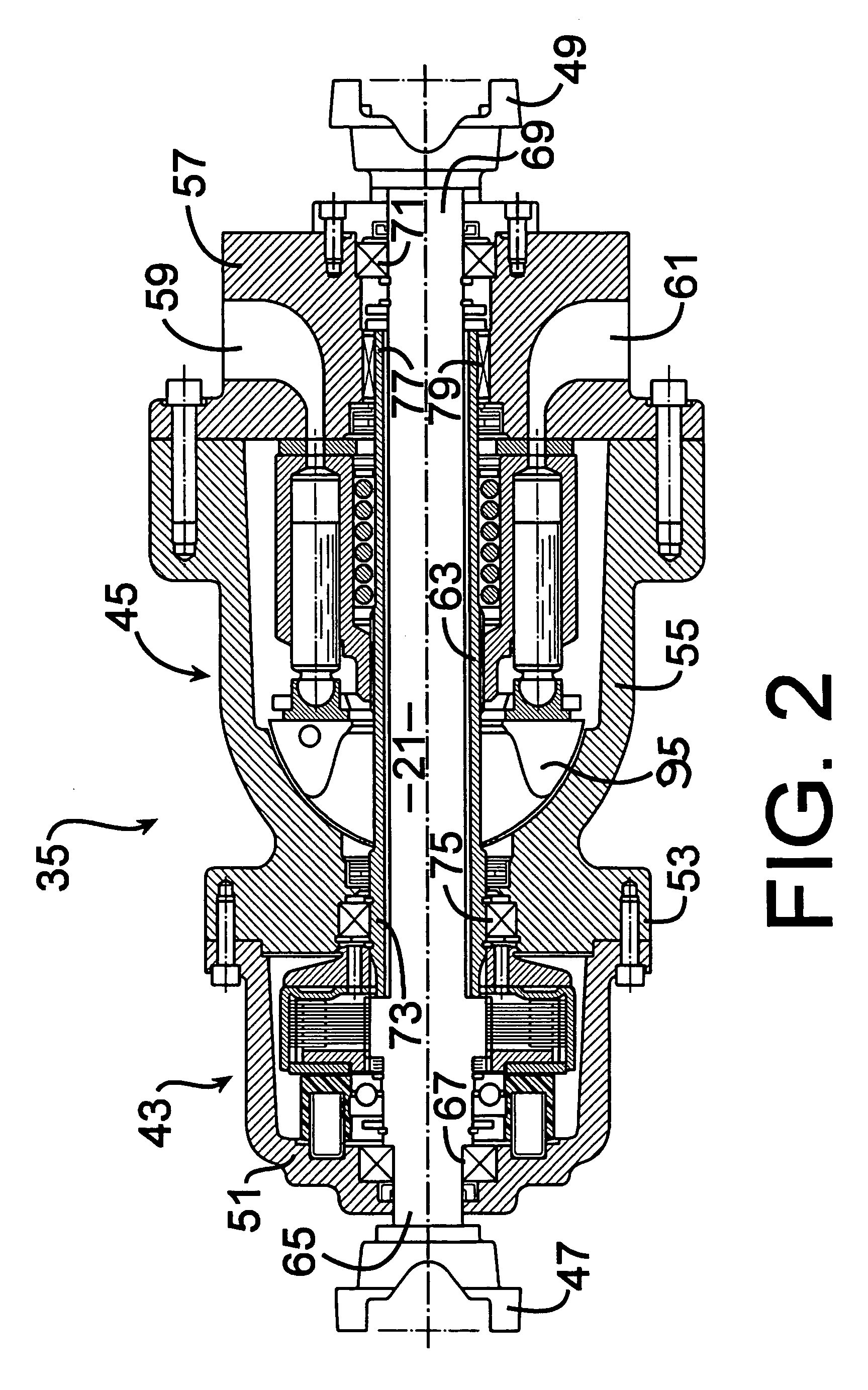
[0011] The above and other objects of the invention are accomplished by the provision of an improved hydraulic drive system adapted for use on a vehicle having an engine and a drive line operable to transmit driving torque from the engine to a drive axle. The drive system includes a hydrostatic pump-motor unit operable, in a pumping mode, to receive drive torque from the drive line and operable, in a motoring mode, to transmit drive torque to the drive line. A high-pressure accumulator is in fluid communication with a first port of the pump-motor unit through a mode valve means whereby, when the pump-motor unit is in the pumping mode, pressurized fluid is communicated from the pump-motor unit to the high pressure accumulator. When the pump-motor unit is in the motoring mode, pressurized fluid is communicated from the high pressure accumulator to the pump-motor unit. A low pressure accumulator is in fluid communication with a second port of the pump-motor unit.
[0012] The improved hydraulic drive system is characterized by a filter circuit disposed between the low pressure accumulator and the pump-motor unit. The filter circuit defines a relatively unrestricted first flow path from the low pressure accumulator to the second port when the pump-motor unit is in the pumping mode. The filter circuit defines a second flow path from the second port to the low pressure accumulator when the pump-motor unit is in the motoring mode. The second flow path comprises one path portion through a filter shut-off valve and a filter element in series, and in parallel therewith, another path portion through a controlled flow restriction, whereby one portion of the fluid flow from the second port flows through the filter element, and the remainder of the fluid flow from the second port flows through the controlled flow restriction.
[0013] In accordance with a more limited aspect of the invention, the hydraulic drive system is characterized by the relatively unrestricted first flow path defined by the filter circuit excluding the filter shut-off valve and the filter element.

Problems solved by technology

First, such a system typically includes not only the high pressure accumulator referred to, but also a low pressure accumulator, which is conducive to a long life of the operating fluid, the presence of these two accumulators in the drive system complicates certain aspects of the configuration and the control of the drive system.
Secondly, the presence of a pump-motor unit, which operates in a pumping mode for part of the vehicle cycle, and in a motoring mode for part of the vehicle cycle, introduces certain additional requirements and complications into the drive system and the controls therefor.
As is well known to those skilled in the hydraulic circuit art, it is not feasible to utilize a conventional filter element in a circuit which experiences reversal of flow as part of its normal operation.
When the pump-motor unit is operating in the pumping mode, the presence of a filter element in series with its inlet restricts pump inlet flow (especially after the filter element has collected a substantial amount of contaminant particles), thus resulting in cavitation of the unit (in the pumping mode) and excessive, undesirable noise emanating from the overall drive system.
At the same time, it is not advisable to locate a filter element in series with the outlet of the unit (when it is operating in the motoring mode) because one result will be an increase in the total pressure drop across the unit, thus reducing the overall efficiency of the drive system.
Another undesirable result would be that, as the filter element collects contamination particles, the pressure drop across the unit would vary, and therefore, the total system performance would also vary.
If the filter element is located in series with the outlet of the unit (in the motoring mode) the filter element could rupture, and catastrophically contaminate the entire system.

Method used


Image

  • Hydraulic drive system and improved filter sub-system therefor
  • Hydraulic drive system and improved filter sub-system therefor
  • Hydraulic drive system and improved filter sub-system therefor

Examples


Embodiment Construction

[0019] Referring now to the drawings, which are not intended to limit the invention, FIG. 1 illustrates a vehicle drive system of the type for which the hydraulic drive system of the present invention is especially well suited. The vehicle system shown schematically in FIG. 1 has four drive wheels W, although it should be understood that the present invention is not limited to a vehicle having four-wheel drive (or even four drive wheels), but could also be used with a vehicle having only two-wheel drive, and in that case, the two drive wheels could be either rear drive wheels or front drive wheels. Operably associated with each of the drive wheels W is a conventional type of wheel brake B, the details of which form no part of the present invention, and the wheel brakes B will be referred to only briefly hereinafter. Preferably, the wheel brakes B are part of an overall EHB (electro-hydraulic brake) system, of the type which is just now becoming well known to those skilled in the art...


PUM


Abstract

A hydraulic drive system (11) of the type including a hydrostatic pump-motor unit (35) having a pumping mode in which the unit pressurizes, from its port (A), a high pressure accumulator (41), and a motoring mode, in which the unit is driven by pressurized fluid from the high pressure accumulator. The system also includes a low pressure accumulator (39) in communication with the opposite port (B) of the pump-motor unit (35), and a filter circuit (107) disposed therebetween. The filter circuit (107) defines an unrestricted first flow path from the low pressure accumulator to the port (B) when the unit is in the pumping mode, and a second flow path from the port (B) to the low pressure accumulator when the unit is in the motoring mode. The second flow path comprises one path portion (125) through a filter shut-off valve (121) and a filter (127) in series, and in parallel therewith, another path portion through a controlled flow restriction (135). Thus, filtration occurs during only the motoring mode, and the percentage of fluid being filtered can be predetermined.

Description

BACKGROUND OF THE DISCLOSURE [0001] The present invention relates to hydraulic drive systems of the type including a pump-motor unit which operates as a pump during a portion of the vehicle operating cycle, and as a motor during another portion of the vehicle operating cycle. Even more particularly, the present invention relates to an improved control circuit for controlling the drive system, and a filter sub-system for use in such a hydraulic drive system. [0002] Although the control circuit and the filter sub-system of the present invention may be utilized in hydraulic drive systems of various types, including such drive systems which effectively serve as the primary vehicle transmission during at least most of the vehicle operating cycle, the present invention is especially advantageous when used on a hydraulic drive system which comprises part of a vehicle hydraulic regenerative braking system, and will be described in connection therewith. [0003] In a vehicle hydraulic drive sy...

Claims


Application Information

Patent Timeline
Patent Type & Authority Applications(United States)
IPC IPC(8): B60K6/12F16D31/02
CPCB60K6/12Y02T10/6208F16D31/02Y02T10/62
Inventor SINGH, RODNEY V.
Owner EATON CORP
Why Eureka
Try Eureka