
Managing method for optimizing capacity of storage

a storage capacity and management method technology, applied in the direction of digital computers, input/output to record carriers, instruments, etc., can solve the problems of inefficient utilization of storage resources, many unused and useless storage areas remain unused, and it is difficult to accurately estimate the capacity utilization in advance and allocate the needed volume. , to achieve the effect of high resource utilization

Inactive Publication Date: 2005-01-20
HITACHI LTD
View PDF23 Cites 35 Cited by
  • Summary
  • Abstract
  • Description
  • Claims
  • Application Information

AI Technical Summary

Benefits of technology

[0010] Further, in another embodiment of the present invention, maximum capacity utilization, minimum capacity utilization, the number of I / O read operations and the number of I / O write operations are periodically obtained in addition to the capacity utilization of the volume allocated to the computer. When the data capacity is constant and the number of I / O write operations to a volume (old volume) is 0 for a certain period, data in the volume is marked as “archive” and is moved to a storage device of low cost so that the capacity of the old device is collected.

Problems solved by technology

In a conventional system, capacity is added, by on-demand from a storage pool, when the volume capacity become short due to insufficient estimation of the capacity being used, at an insufficient time point.
It is difficult to accurately estimate the capacity utilization in advance and to allocate the needed volume.
In an environment in which storage devices are intensively consolidated and many volumes exist, it will happen that many unused and useless storage areas remain unused.
Since such unused storage areas in volumes are unused, but cannot be utilized as the storage pool, the storage resources can not be efficiently used.

Method used


Image

  • Managing method for optimizing capacity of storage
  • Managing method for optimizing capacity of storage
  • Managing method for optimizing capacity of storage

Examples


Embodiment Construction

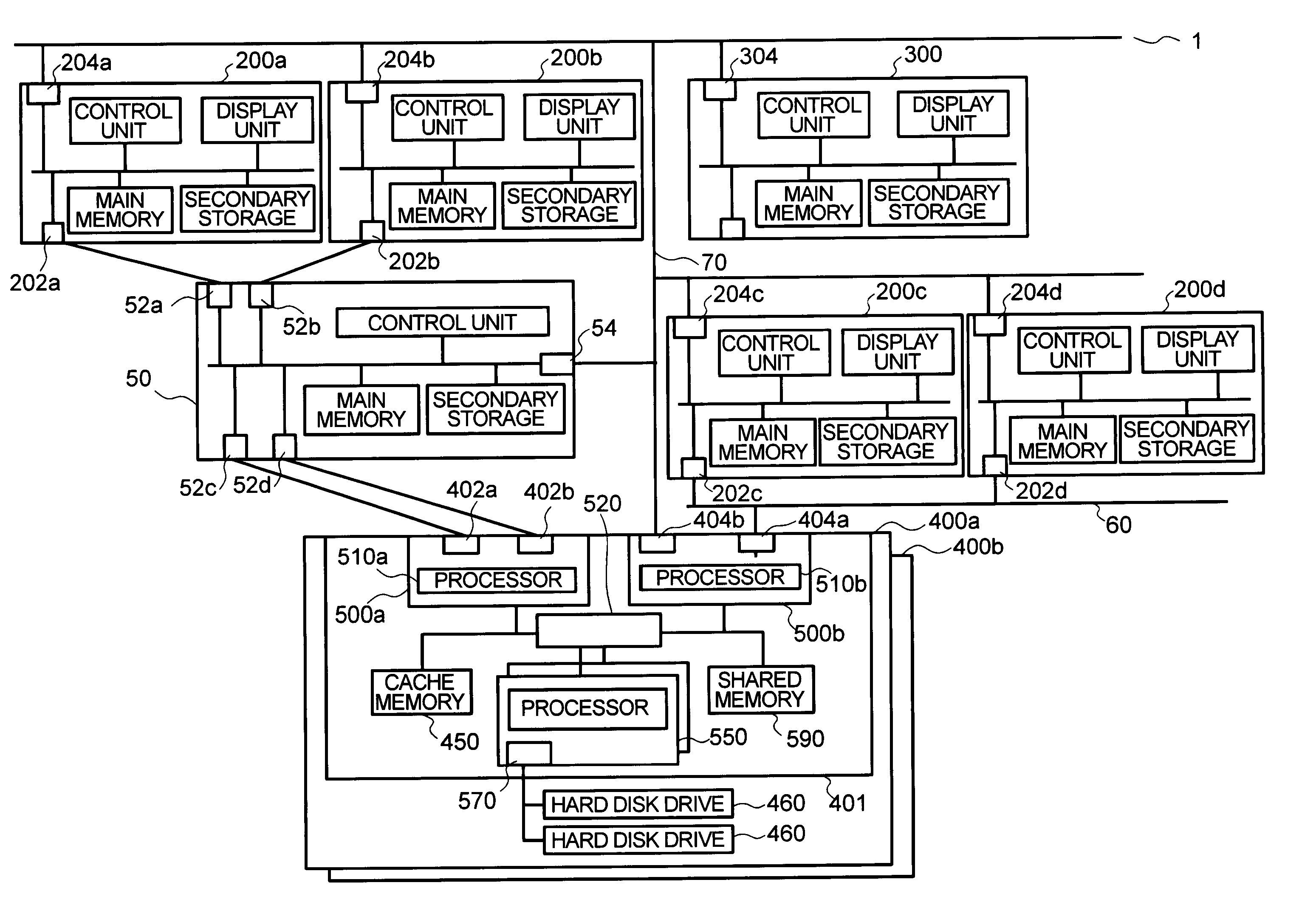
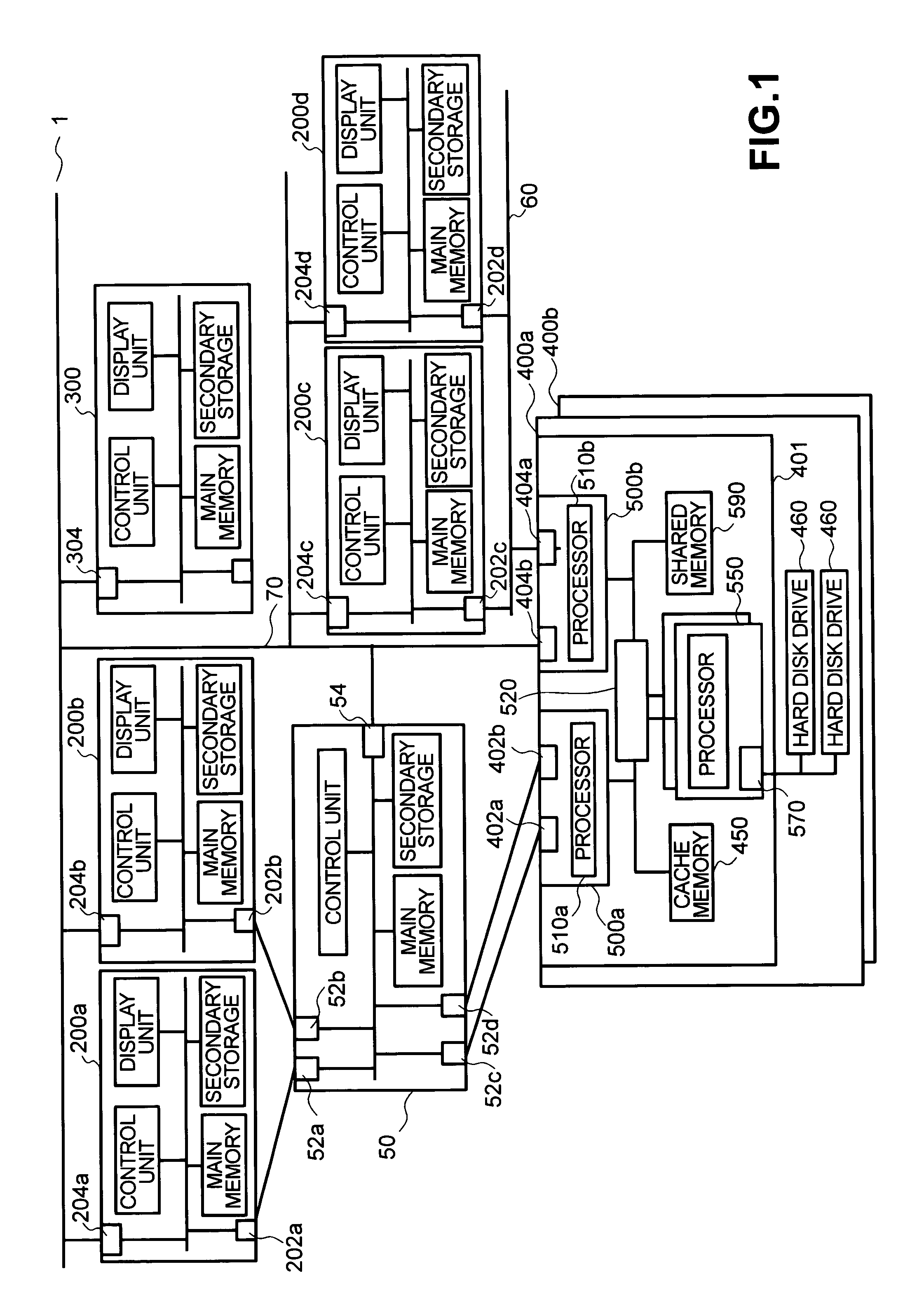
[0022]FIG. 1 is a block diagram showing an embodiment of a computer system according to the present invention. The computer system 1 includes computers 200a, 200b, 200c, 200d (generally referred to as “computer 200”), a management computer 300, a fibre optic channel switch 50, Internet Protocol (hereinafter called “IP”) networks 60 and 70, and a storage apparatus 400 (400a, 400b).

[0023] The storage apparatus 400 is connected to computers 200a and 200b through the fibre optic channel switch 50. The storage apparatus 400 is also connected to computers 200c and 200d through the IP network 60. The storage apparatus 400 is further connected to the management computer 300 by the IP network 70.

[0024] The computers 200a and 200b, which are connected to the storage apparatus 400 through the fibre optic channel switch 50, transfer data by using SCSI Protocol over Fibre Channel (hereinafter called “FCP”) protocol. The computers 200c and 200d, which are connected to the storage apparatus 400 ...


PUM


Abstract

In an environment in which storages are intensively collected, many unused areas are generated and no storage resources can be efficiently used as a storage pool. The capacity utilization (data capacity) of a storage device (volume) allocated to a computer is obtained and future capacity utilization is estimated from a change in the data capacity. Upper limit securing capacity and lower limit securing capacity showing the upper and lower limits of appropriate allocating capacity calculated from this estimated capacity utilization, and the capacity of the storage device are compared with each other. When the capacity of the storage device (old device) is greater than the upper limit securing capacity, the storage device (new device) of the lower limit securing capacity or more and the upper limit securing capacity or less is allocated from the storage pool, and the old device is collected in the storage pool.

Description

BACKGROUND OF THE INVENTION [0001] The present invention relates to a method for centrally managing plural storage devices. [0002] In recent years, a technique for connecting a computer and plural storage devices by way of a network (storage area network (SAN)) and centrally managing the plural storage devices connected to the SAN has been proposed. [0003] As a method for managing plural storage devices connected to a SAN, there is a technique for centrally managing a storage device (volume), among the plural storage devices connected to the SAN, as a storage pool, and efficiently using the memory capacity of the storage device connected to the SAN. [0004] In a conventional system, capacity is added, by on-demand from a storage pool, when the volume capacity become short due to insufficient estimation of the capacity being used, at an insufficient time point. (For example, see (Patent Literature 1) JP-A-2002-222061 at p. 9, FIG. 11). [0005] It is difficult to accurately estimate the...

Claims


Application Information

Patent Timeline
IPC IPC(8): G06F3/06G06F13/10G06F12/00G06F15/173
CPCG06F3/0608G06F3/067G06F3/0653G06F3/0631
Inventor FUJITA, TAKAHIROKANEDA, YASUNORI
Owner HITACHI LTD
Learn More