
Near shore port security barrier

a security barrier and shore port technology, applied in the field of security systems, can solve the problems of difficult if not impossible to distinguish from other non-threatening watercraft, high cost of security barriers, and asymmetric threats to ocean going vessels docked at ports

Inactive Publication Date: 2005-01-20
THE UNITED STATES OF AMERICA AS REPRESENTED BY THE SECRETARY OF THE NAVY
View PDF7 Cites 18 Cited by
  • Summary
  • Abstract
  • Description
  • Claims
  • Application Information

AI Technical Summary

Benefits of technology

[0007] The present invention overcomes some of the disadvantages of the port security barriers utilized in the past in that it comprises a relatively simple design, and highly effective port security barrier which is adapted for use with a vessel to prevent damage to the vessel caused by an attack from an explosive laden watercraft. Since the near shore port security barrier is designed to be easily moved from one vessel to another vessel, the near shore port security barrier provides a substantial deterrence to an attack while the vessel is docked at a port facility.
[0011] When an attack from a hostile craft occurs and the attacker attempts to disconnect the barrier modules, the near shore port security barrier provides sufficient delay time for security forces to respond to the threat.
[0013] When the attacking craft is filed with explosives the near shore port security barrier provides a minimum standoff distance to prevent catastrophic damage to critical ship systems. The combination of barrier material and standoff distance attenuates the effects of munitions and explosives when these explosive are used to attack a ship. The near shore port security barrier is modular so that the barrier material and standoff distance can be adjusted to meet specific existing or evolving threats.

Problems solved by technology

Ocean going vessels docked at a port, whether commercial or military, are vulnerable to by asymmetric threats, such as small watercraft laden with explosive or munitions.
These threat watercraft can be pleasure boats or other commercially available watercraft which are difficult if not impossible to distinguish from other non-threatening watercraft.
Other more expensive security barriers provide a physical security barrier for the port facility but not for individual vessels within the facility in the event the barrier is penetrated.

Method used


Image

  • Near shore port security barrier
  • Near shore port security barrier
  • Near shore port security barrier

Examples


Embodiment Construction

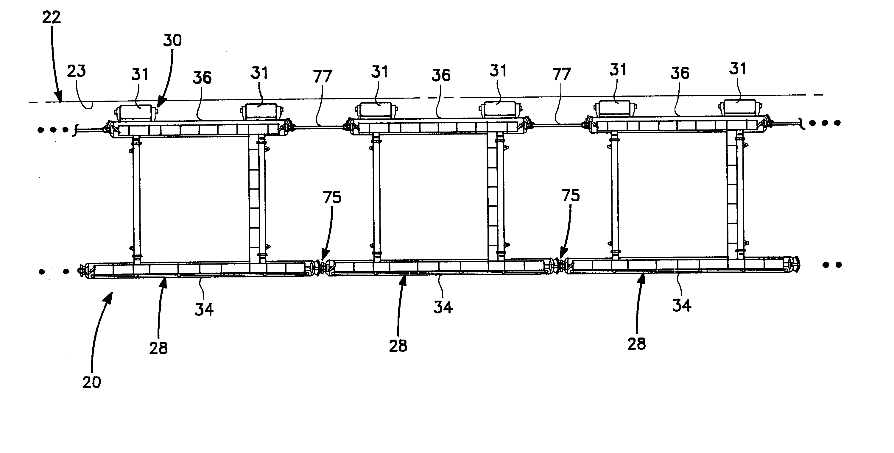
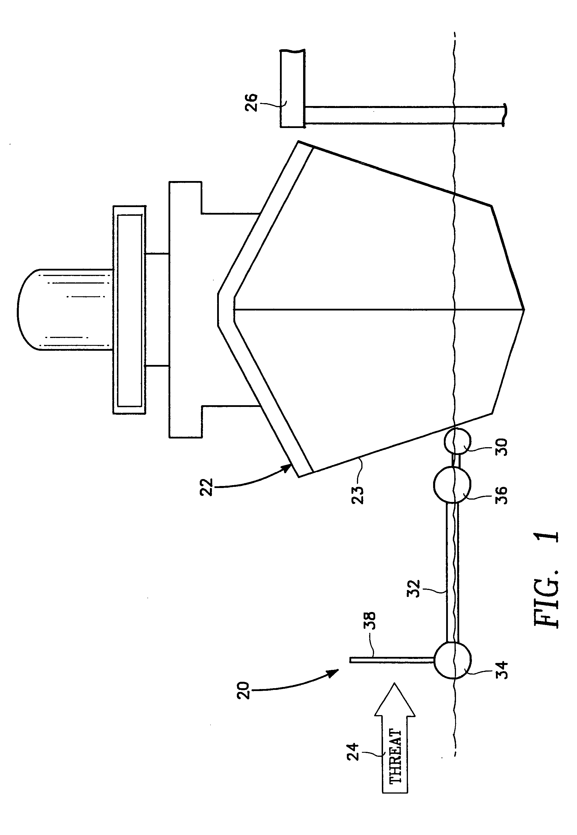
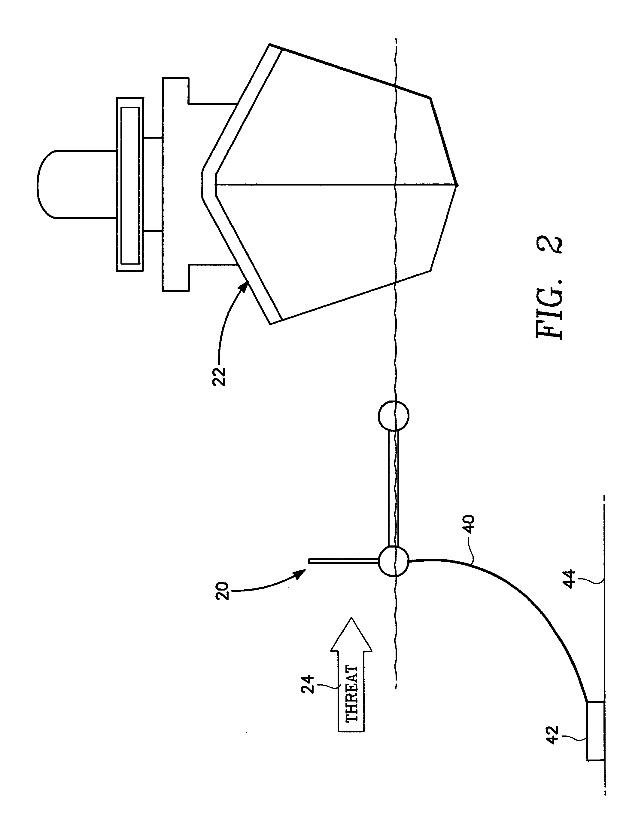
[0015] Referring to FIGS. 1-4, the in near shore port security barrier 20 comprises a barrier which protects an ocean going vessel 22 from attack by a threat watercraft 24 while docked at a pier 26 at harbor facility or at a set distance from the pier 26 depending upon on a perceived threat (for example threat watercraft 24) and port characteristics. The threat watercraft 24 may be a pleasure boat or other small high speed vessel, which is laden with explosives or munitions that are detonated when the watercraft 24 is in proximity to vessel 22. When the explosive materials aboard watercraft 24 are triggered severe damage to vessel 22 generally occurs.

[0016] The near shore port security barrier 20 comprises a plurality of barrier modules 28 (FIG. 3) which are fitted together in the manner illustrated in FIG. 4. Each module includes fendering system 30, which protects vessel 22 and near shore port security barrier 20 during normal port operations and also function to dissipate energy...


PUM


Abstract

A near shore port security barrier for protecting a vessel docked at a port facility from an incoming waterborne craft which is being used to inflict damage on the vessel. The near shore port security barrier consist of a plurality of floating barrier modules connected to one another and placed adjacent the hull of the vessel the near shore port security barrier is designed to protect. A wire mesh barrier fence, which is positioned on the outer perimeter of each floating barrier module is also provided to protect the vessel.

Description

BACKGROUND OF THE INVENTION [0001] 1. Field of the Invention [0002] The present invention relates generally to a security system which protects vessels docked in a port from being damage by explosive laden watercraft. More particularly, the present invention relates to an near shore port security barrier which utilizes a fixed fence structure attached to a floating barrier pontoon to protect ships docked at a port. [0003] 2. Description of the Prior Art [0004] Ocean going vessels docked at a port, whether commercial or military, are vulnerable to by asymmetric threats, such as small watercraft laden with explosive or munitions. These threat watercraft can be pleasure boats or other commercially available watercraft which are difficult if not impossible to distinguish from other non-threatening watercraft. Because of the structure and layout of port facilities, it is not very difficult for a small hostile watercraft to pull alongside a moored vessel and then detonate explosives causi...

Claims


Application Information

Patent Timeline
Patent Type & Authority Applications(United States)
IPC IPC(8): E02B3/20E02B15/04F41H11/05
CPCE02B3/20F41H11/05E02B15/085E02B15/08
Inventor NIXON, LAURENCE G.SLAUGHTER, STEPHENTAYLOR, ROBERT J.SEELIG, WILLIAM
Owner THE UNITED STATES OF AMERICA AS REPRESENTED BY THE SECRETARY OF THE NAVY
Learn More