
Bearing and screw compressor

Active Publication Date: 2005-01-20
KOBE STEEL LTD
View PDF2 Cites 15 Cited by
  • Summary
  • Abstract
  • Description
  • Claims
  • Application Information

AI Technical Summary

Benefits of technology

[0017] It is a first object of the present invention to provide a bearing being constituted by a plural-layer slide member having a resin layer in a slide portion between it and a thrust member or a shaft, but nevertheless capable of detecting its temperature accurately, as well as a screw compressor having the bearing.
[0018] It is a second object of the present invention to provide an oil cooled screw compressor which, even in the event of occurrence of foaming in oil for lubricating radial bearings and thrust bearings, can prevent the occurrence of mechanical troubles such as galling and scratching.
[0020] In the bearing of the first invention, a temperature sensing portion of the temperature sensor for detecting the temperature of the temperature measuring metallic member may be brought into contact with the temperature measuring metallic member. More specifically, the bearing of this first invention may have a construction wherein the temperature of the temperature measuring metallic member fitted from the resin layer side of the bearing constituted by a plural-layer slide member into the fitting hole having a depth exceeding the thickness of the resin layer is detected directly by the temperature sensing portion of the temperature sensor. According to this construction, since the temperature measuring metallic member far superior in thermal conductivity to the resin layer, it is possible to detect the temperature of the bearing accurately.
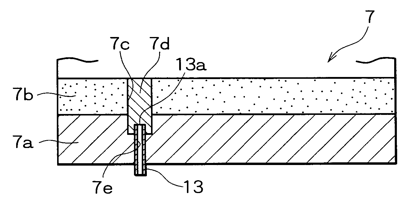
[0021] In the bearing of the first invention, the temperature sensing portion of the temperature sensor for detecting the temperature of the temperature measuring metallic member may be positioned near the temperature measuring metallic member. More specifically, the bearing of this first invention may have a construction wherein the temperature of the backing strip transmitted thereto from the temperature measuring metallic member is detected, the temperature measuring metallic member being fitted from the resin layer side of the bearing constituted by a plural-layer slide member into the fitting hole having a depth exceeding the thickness of the resin layer, that is, the temperature of the temperature measuring metallic member is detected indirectly by the temperature sensing portion of the temperature sensor. According to this construction, although the detection accuracy is inferior to the preceding case where the temperature of the temperature measuring metallic member is detected directly, the temperature of the bearing can be detected accurately because the temperature measuring metallic member and the backing strip are far superior in thermal conductivity than the resin layer.
[0025] According to the second invention, the temperature of the resin bearing can be estimated easily by detecting the temperature of the metallic bearing which is higher in temperature conductivity than the resin bearing, with the temperature sensor so that it is possible to prevent damage of the bearings. Besides, the sliding metallic member of the metallic bearing, e.g., white metal, is lower in melting point than the resin layer of the resin bearing, for example, formed by polytetrafluoroethylene (“PTFE” hereinafter) so that the strength of the metallic bearing becomes low with a rise in temperature, but there is no fear of damage to the entire bearing because the resin bearing undertakes the thrust force.
[0028] In the screw compressor of the third invention, oil after separation and recovery from discharge gas is supplied as lubricating oil to the radial bearings and / or the thrust bearings by the oil supply means. Even if foaming occurs in the oil due to pressure reduction and an oil film breaks on a pressure receiving surface of any of the radial bearings, there is no fear of direct contact between the metal of the radial bearing and the associated rotor shaft because the bearing surface is covered with the resin material, nor is there any fear of direct contact between the thrust member fitted on each rotor shaft and the metal of the thrust bearings. Thus, there is no fear of occurrence of a mechanical trouble caused by foaming such as galling or scratching in the rotor shafts, thrust members, radial bearings and thrust bearings.

Problems solved by technology

However, if the oil film breaks or the thrust member or the shaft and the bearing come into direct contact with each other, the temperature of the bearing itself rises rapidly into an abnormally high temperature, resulting in damage of machine having such bearings, thus leading to a serious accident such as a stop of operation.
However, when such a construction is applied to the bearing related to the first conventional example wherein the slide portion is formed by a resin layer, even if there occurs a rise in temperature due to breaking of the oil film or due to direct contact of the thrust member or shaft with the bearing.
However, there sometimes is a case where the temperature is not transmitted to the temperature sensor and a trouble of the bearing cannot be detected, because the resin is much lower in thermal conductivity than the metal.
Consequently, the rotor shaft 71 and the radial bearing 72 come into direct contact with each other and there arises a fear of occurrence of a mechanical trouble such as galling or scratching of the shaft and the bearing.
However, it does not disclose any means for eliminating the trouble caused by the foregoing foaming of oil.

Method used


Image

  • Bearing and screw compressor
  • Bearing and screw compressor
  • Bearing and screw compressor

Examples


first embodiment

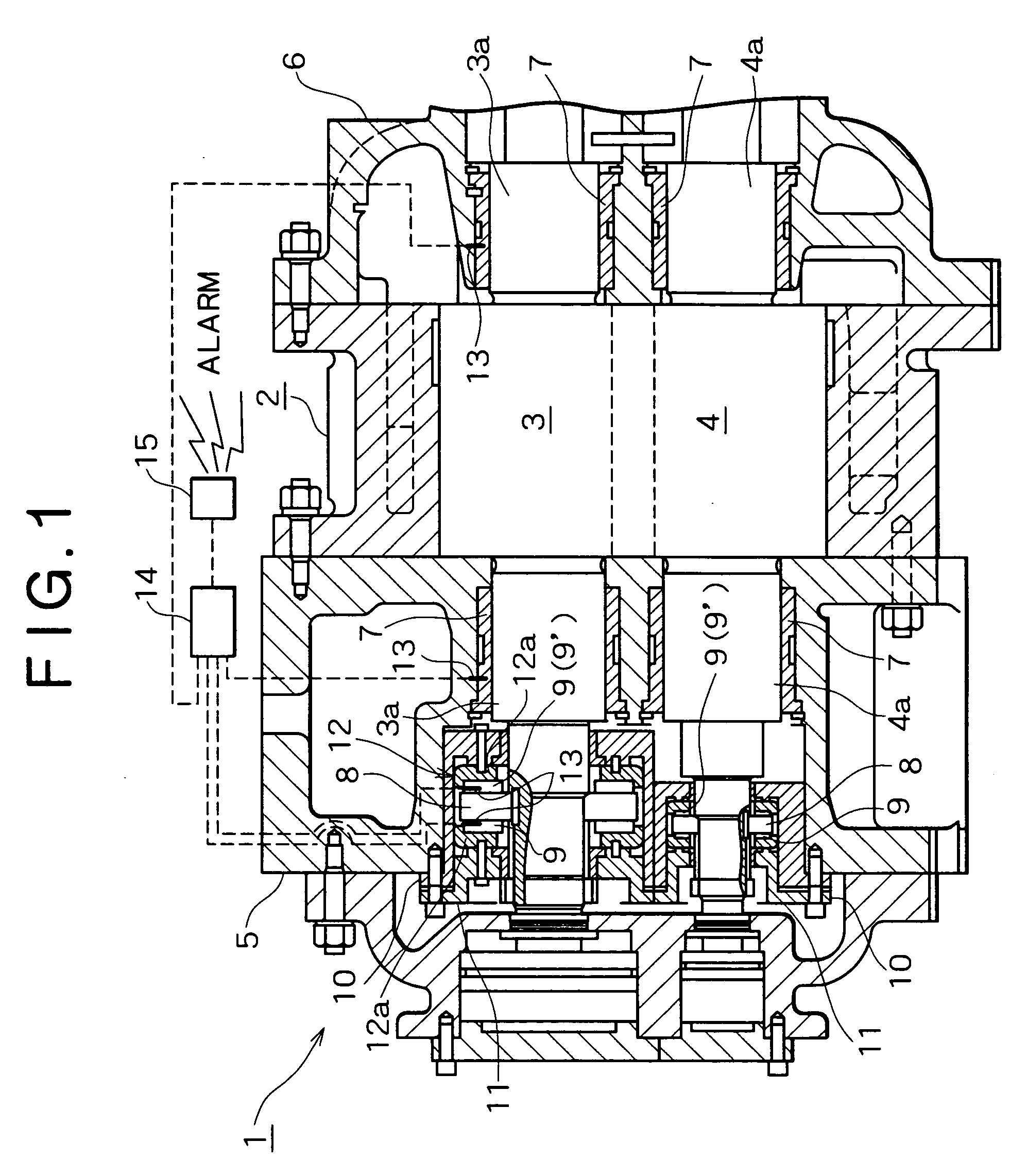
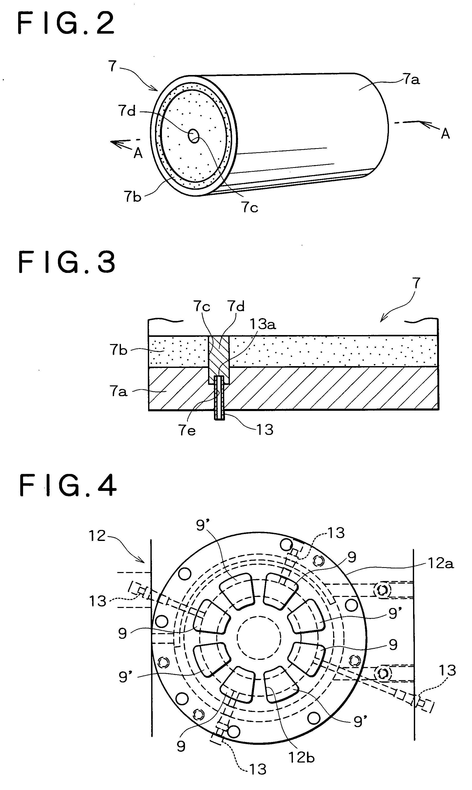
[0048] A screw compressor and bearings according to the present invention will be described below with reference to the accompanying drawings. FIG. 1 is a sectional view of a principal portion of the screw compressor, showing in what state bearings are arranged in the screw compressor. FIG. 2 is a perspective view of a radial bearing, FIG. 3 is a sectional view taken on line A-A in FIG. 2. FIG. 4 illustrates a tilting pad thrust bearing as seen from a thrust bearing side, FIG. 5 is a perspective view of a thrust bearing, and FIG. 6 is a sectional view taken on line B-B in FIG. 5.

[0049] In the figures, the reference numeral 1 denotes a screw compressor having bearings according to the present invention. The screw compressor 1 is provided with a casing 2. A pair of intermeshing female and male screw rotors 3, 4 are housed within the casing 2. Of the pair of female and male screw rotors 3, 4, the screw rotor 3 is rotated by a motor (not shown), while the other screw rotor 4 is rotated ...

second embodiment

[0060] Radial bearings 7 used in the screw compressor of this second embodiment are each constituted as shown in FIGS. 7 and 8. In each of the radial bearings 7, a fitting hole 7c having a depth which exceeds the thickness of a resin layer 7b is formed from the resin layer 7b side. A temperature measuring metallic member 7d formed of a white metal having a melting point lower than the melting point of the resin layer 7b is fitted in the fitting hole 7c so that one end face thereof constitutes a part of an inner periphery surface of the resin layer 7b. Further, a temperature measuring hole 7e having a depth which reaches a position near the temperature measuring metallic member 7d is formed in the backing strip 7a from an outer side of the backing strip. A sheath type temperature sensor 13 is inserted into the temperature measuring hole 7e. A temperature sensing portion 13a formed at the tip of the temperature sensor 13 is in contact with the bottom of the temperature measuring hole ...

third embodiment

[0065] A description will now be given of the operation of the tilting pad thrust bearing 12 in accordance with this According to the tilting pad thrust bearing 12, the temperature of the thrust bearing 9′ can be estimated easily by detecting the temperature of the metallic bearing high in temperature conductivity through the temperature sensor 13, so that it is possible to prevent damage of the tilting pad thrust bearing. Since the white metal layer in the thrust bearing 19 is lower in melting point than the resin layer of PEEK in the thrust bearing 9′, so that the strength of the thrust bearing 19 and hence the thrust force bearing effect of the thrust bearing 19 are deteriorated as the temperature rises. However, since the thrust force is borne by the thrust bearing 9′, there is no fear of damage of the tilting pad thrust bearing 12.

[0066] Preferred thickness of the resin layer and diameter of the temperature measuring metallic member in the second and third embodiment are the s...


PUM


Abstract

In a bearing constituted by a plural-layer slide member, the plural-layer slide member comprises a resin layer of polytetrafluoroethylene as a slide member and a backing strip to which the resin layer is bonded. A fitting hole having a depth exceeding the thickness of the resin layer is formed from the resin layer side. A temperature measuring metallic member formed of a white metal is fitted in the fitting hole. A temperature sensor is positioned within the temperature measuring metallic member. This bearing permits an accurate detection of its temperature. Further, in an oil cooled screw compressor having a bearing lubricating oil supply pipe, a slide surface of the bearing is covered with polyether ether ketone. Even if foaming occurs in the oil, it is possible to prevent the occurrence of a mechanical trouble such as galling.

Description

BACKGROUND OF THE INVENTION [0001] 1. Field of the Invention [0002] The present invention relates to an improvement of a bearing and a screw compressor and more particularly to a bearing capable of detecting a temperature and a screw compressor having the bearing. Especially, the present invention is concerned with an oil cooled screw compressor of the type in which oil after separation and recovery from discharge gas is supplied as lubricating oil. [0003] 2. Description of the Related Art [0004] A screw compressor has a casing for housing therein a pair of female and male screw rotors meshed with each other. End portions of rotor shafts of each of the pair of screw rotors are supported by radial bearings. On the other hand, in each of the pair of female and male screw rotors, a pair of tilting pad thrust bearings for bearing a thrust force developed on the screw rotor are mounted at the end portion of one rotor shaft. The tilting pad thrust bearings are disposed on both sides of a ...

Claims


Application Information

Patent Timeline
IPC IPC(8): F16C17/06F16C17/24
CPCF16C17/24F16C17/06F16C2360/43
Inventor YOSHIMURA, SHOJIAMANO, YASUSHIOHAMA, TAKAO
Owner KOBE STEEL LTD
Learn More