
Method and apparatus for attaching an ink jet filter to an ink cartridge

a technology of ink jet filter and ink cartridge, which is applied in the field of methods for attaching ink jet filter to ink cartridge, can solve the problems of increasing the difficulty of attaching the filter to the frame, reducing the quality and operation of the printhead, and high cost of stainless steel materials

Active Publication Date: 2005-01-20
FUNAI ELECTRIC CO LTD
View PDF20 Cites 5 Cited by
  • Summary
  • Abstract
  • Description
  • Claims
  • Application Information

AI Technical Summary

Benefits of technology

[0010] The invention provides a number of advantages over conventional apparatus and methods for attaching filter materials in ink jet cartridges. In particular, the process and apparatus enables use of a synthetic filter material which is less costly than a metal filter material. The apparatus also enables welding of synthetic filter materials to a filter tower structure while maintaining the filter material in a desired shape. For example, contoured or tented filters may be attached to filter towers using the apparatus according to the invention. Another advantage of the invention is that the process of laser welding is substantially a non-contact process thereby avoiding abrasion of the filter material. As compared to ultrasonic welding, the laser welding process according to the invention does not cause vibrations during the welding process which can generate particles or otherwise damage the filter.
is that the process of laser welding is substantially a non-contact process thereby avoiding abrasion of the filter material. As compared to ultrasonic welding, the laser welding process according to the invention does not cause vibrations during the welding process which can generate particles or otherwise damage the filter.

Problems solved by technology

Particles larger than the flow features of the printhead can adversely affect the operation of the printhead thus dramatically decreasing the quality and operation of the printhead.
However, the cost of such stainless steel material is relatively high.
However, the replacement of metal filter material with synthetic filter materials, makes attachment of the filter to the frame much more difficult.
On the other hand, if the melting temperature of the frame is higher than that of the filter material, the filter will be melted and thinned under pressure, and in some cases the stitches around the perimeter of the filter may be damaged thereby weakening the filter.
However, when ultrasonics are applied to synthetic filter materials, the high frequency mechanical vibration may cause loose stitches, broken stitches, and particle generation.
Loose stitches and broken stitches may cause the filter to fail prematurely.
Particle generation may inhibit the flow of ink to and in the ink jet printheads thereby reducing print quality.
Another disadvantage of plastic filter materials is that these materials are generally less stiff than metal filter materials and are thus prone to bending, stretching, and wrinkling during the attachment process.

Method used


Image

  • Method and apparatus for attaching an ink jet filter to an ink cartridge
  • Method and apparatus for attaching an ink jet filter to an ink cartridge
  • Method and apparatus for attaching an ink jet filter to an ink cartridge

Examples


Embodiment Construction

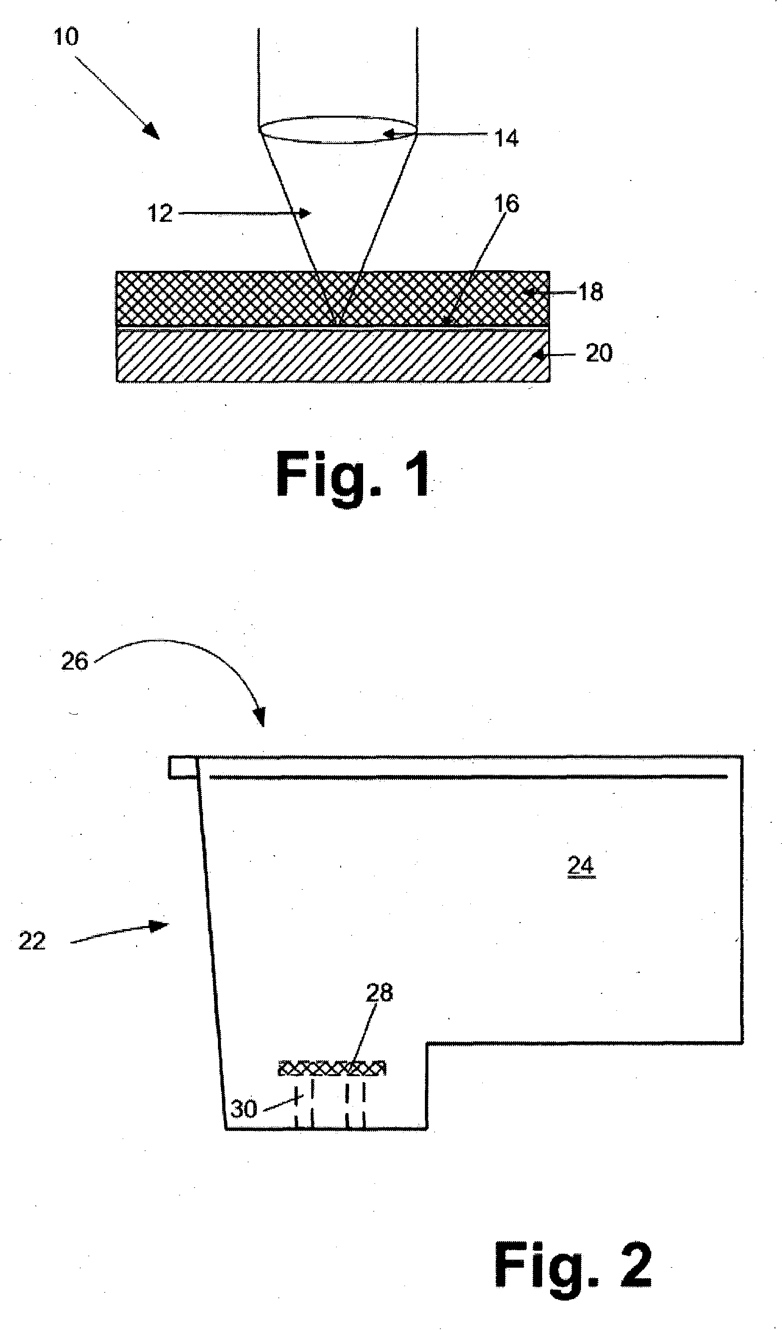
[0023] With reference to FIG. 1, a schematic representation of a laser transmission welding process 10 for attaching a synthetic filter to a filter tower structure is shown. According to the process, a laser beam 12 is focused through a lens 14 onto an interface 16 between a first material 18 to be welded to a second material 20. For this process, it is important that at least one of the two materials being joined together be substantially transparent to the laser beam 12.

[0024] The material facing the laser source, the first material, may preferably be clear or colored provided the coloring material or pigment does not significantly affect the transmission of the laser beam through the material. The second material is placed on a side of the first material opposite the laser beam side of the first material. The second material must be able to absorb the laser beam 12 so that it heats up and melts during the welding process.

[0025] It is also important that the two materials be in ...


PUM

PropertyMeasurementUnit
speedaaaaaaaaaa
wavelengthsaaaaaaaaaa
pressureaaaaaaaaaa

Abstract

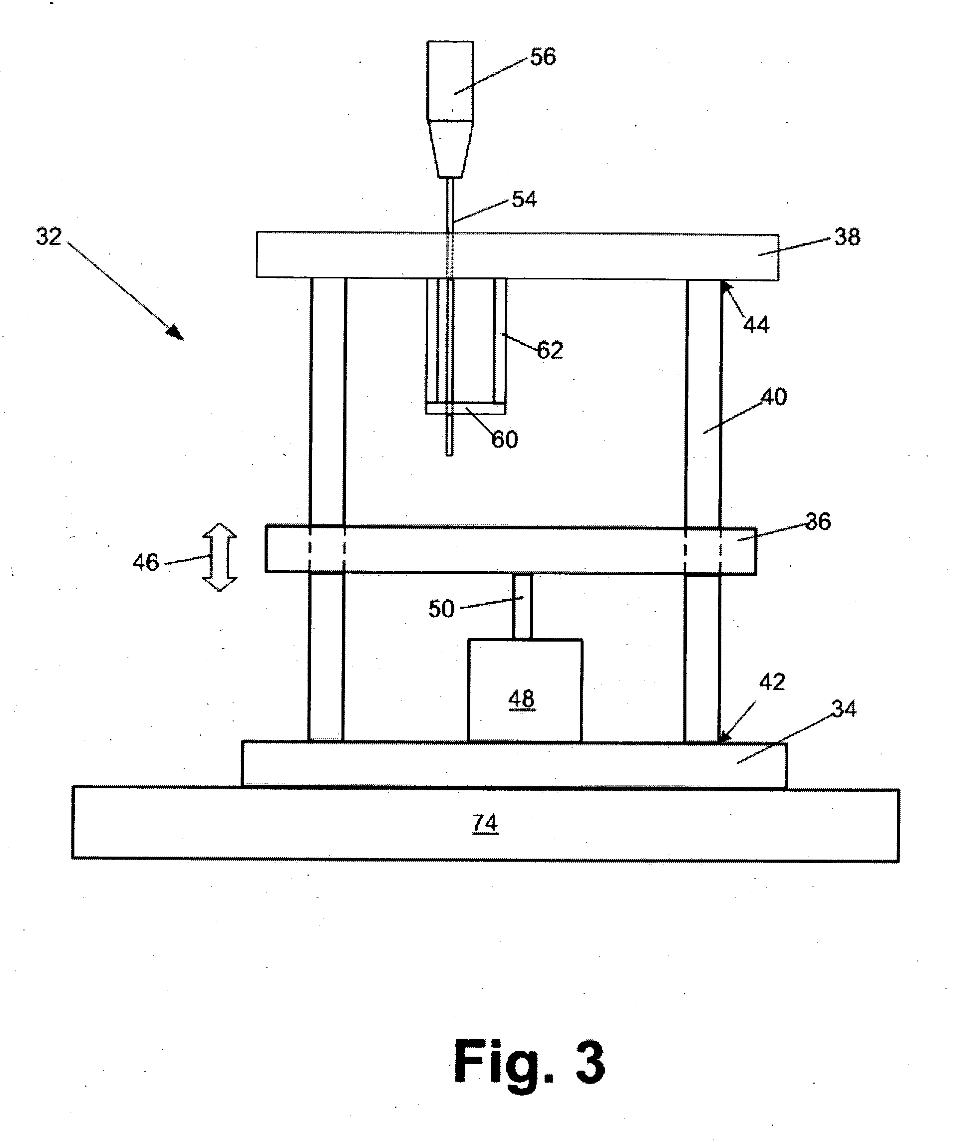
An apparatus for a laser transmission welding process for attaching a synthetic filter material to a filter tower frame in an ink jet printer cartridge. The apparatus includes a laser beam source and a filter clamping fixture containing a base, slide rods attached on first ends thereof to the base, an optics support plate attached to second ends of the slide rods, a movable platform for holding an ink cartridge slidably disposed on the slide rods between the base and the optics support plate, a platform moving device for translating the platform to and from a laser welding position, a laser beam transparent plate suspended by support legs from the optics support plate to a position between the movable platform and the optics support plate. The apparatus greatly improves synthetic filter attachment to a filter tower frame in an ink cartridge.

Description

FIELD OF THE INVENTION [0001] The invention relates to methods for attaching ink jet filters to an ink cartridge for an ink jet printer, and in particular to apparatus for reliable filter attachment to the cartridge. BACKGROUND [0002] Ink jet printers have achieved wide acceptance in the field of printing and continue to make great strides towards high speed, high quality printing. In order to improve the quality and speed of printing, nozzle plates having a larger number of smaller orifices are provided. As the size of the orifices continue to decrease, components of the ink cartridge assembly become increasingly more important. A component of the ink cartridge that is particularly important for proper operation of an ink jet printhead attached to the cartridge is a filter disposed between an ink reservoir and a flow path for ink to the printhead. The filter is the first and most important line of protection for large or foreign particles entering ink flow features of the printhead...

Claims


Application Information

Patent Timeline
Patent Type & Authority Applications(United States)
IPC IPC(8): B41J2/175
CPCB29C65/1616B29C66/8322B29C65/1654B29C65/1661B29C65/1667B29C65/1674B29C65/1687B29C65/1696B29C66/80B29C66/81267B29C66/8242B29C66/863B29L2012/00B29L2031/14B29L2031/737B29L2031/767B41J2/17563B29C65/1638B29C65/1677B29C66/5326B29C66/5346B29C66/61B29C66/81415B29C66/81422B29C66/81423B29C66/81429B29C66/81431B29C66/81611B29C65/1635B29C66/112B29C66/114B29C66/24221B29C66/65B29C66/71B29C66/73921B29K2995/0027B29K2069/00B29K2033/12
Inventor KWAN, KIN MINGSHADWICK, DAVID T.SINGH, JEANNE M. SALDANHASPIVEY, PAUL T.WHITNEY, JON B.GORDON WHITNEY, JULIE A.
Owner FUNAI ELECTRIC CO LTD
Learn More