Device for absorbing floor-landing shock for legged mobile robot
a mobile robot and floor-landing technology, which is applied in the field of landing shock absorbers, can solve the problems of sudden increase in hydraulic oil pressure, affecting the size reduction and weight reduction of each leg, and unstable posture of the robot, so as to enhance the damping effect of the landing shock absorber of the present invention, enhance the impact load reduction effect, and enhance the effect of compressible fluid outflow resistan
- Summary
- Abstract
- Description
- Claims
- Application Information
AI Technical Summary
Benefits of technology
Problems solved by technology
Method used
Image
Examples
first embodiment
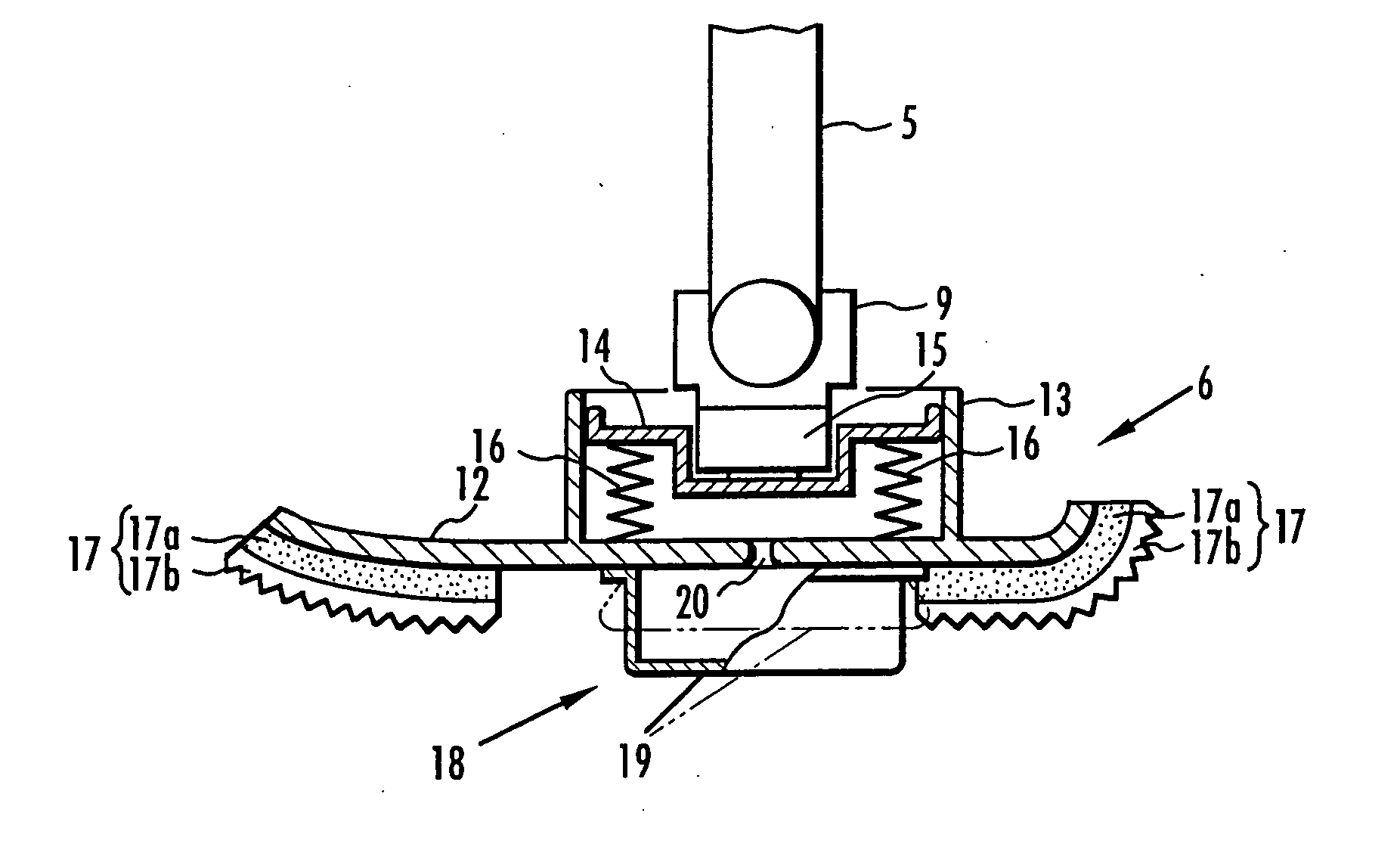
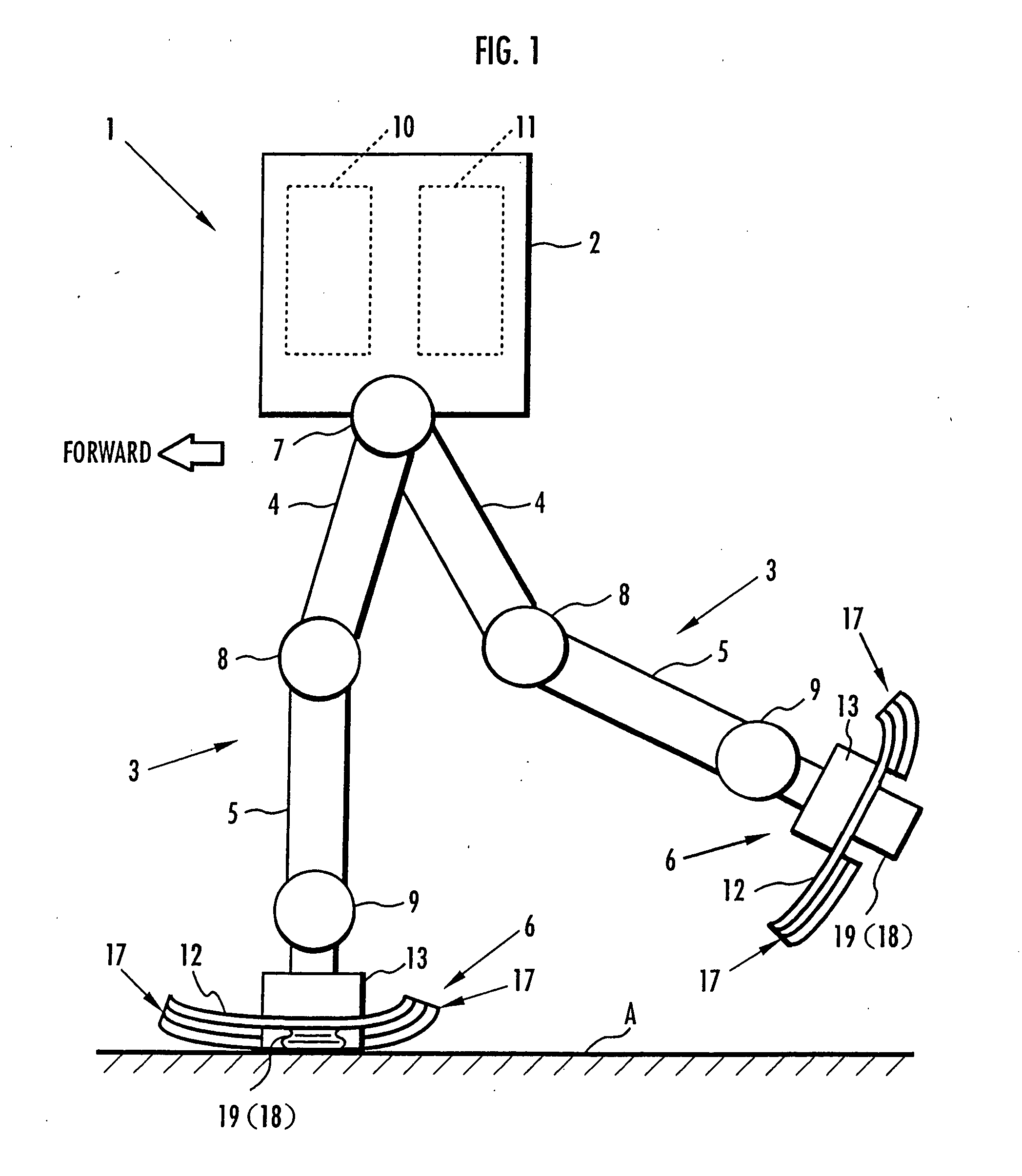
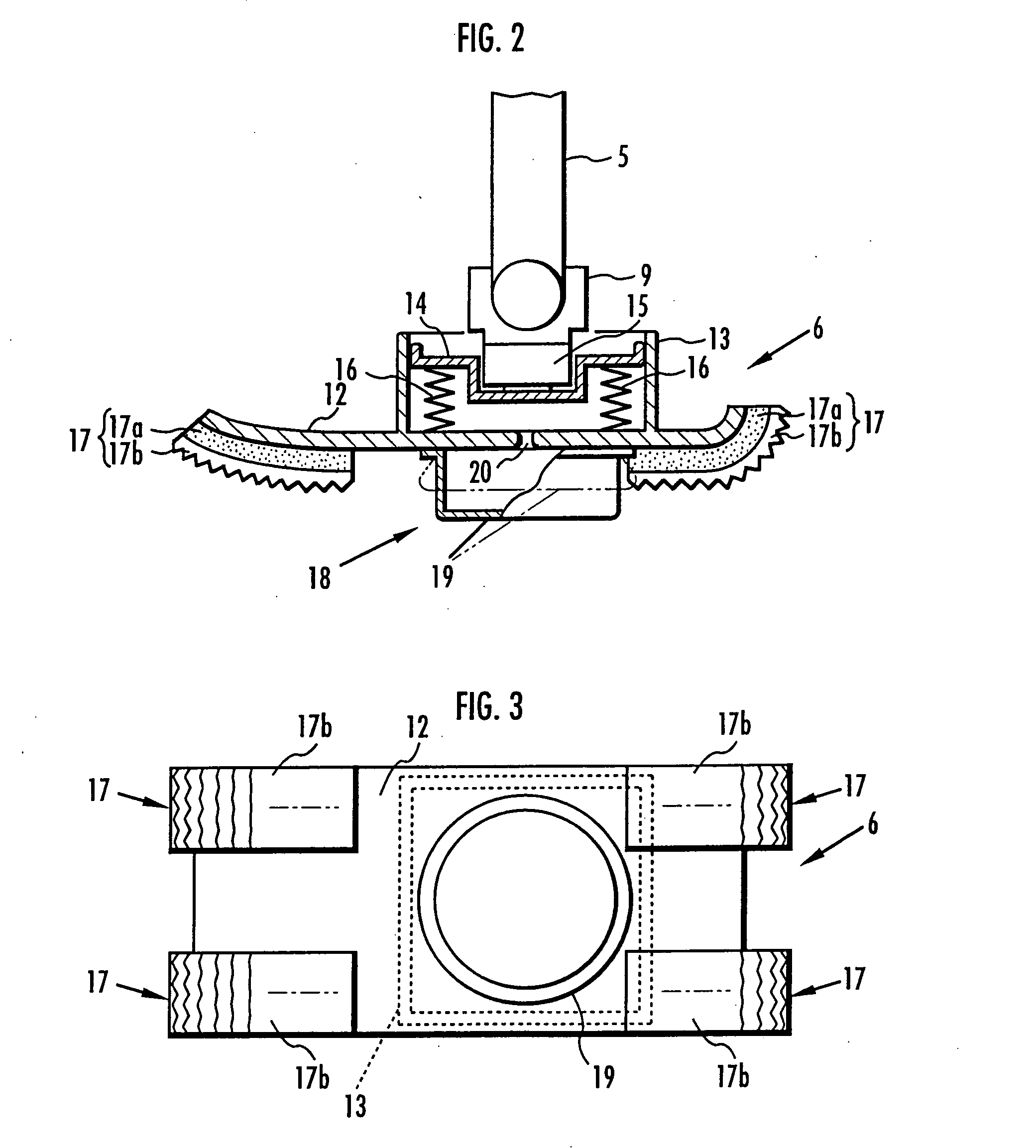
[0048] Referring to FIGS. 1 through 5, the present invention is described. FIG. 1 is a side view showing an overall basic configuration of a legged mobile robot 1 of the present embodiment in schematic form. As shown in FIG. 1, for example, the legged mobile robot 1 of the present embodiment is a biped mobile robot comprising a pair of (two) legs 3, 3 extendedly disposed from a lower end portion of its upper body 2 (torso). Further, arms and a head may be attached on the upper body 2.
[0049] Each leg 3 is constructed by connecting a thigh 4, a lower leg 5, and a foot mechanism 6 in the order listed through a hip joint 7, a knee joint 8, and an ankle joint 9 from the lower end portion of the upper body 2. More specifically, each leg 3 is adapted to be configured with the thigh 4 extendedly disposed from the lower end portion of the upper body 2 through the hip joint 7, the lower leg 5 connected to a far end portion of the thigh 4 through the knee joint 8, and the foot mechanism 6 conn...
third embodiment
[0082] Subsequently, referring to FIG. 7(a) and FIG. 7(b), the present invention is described. FIG. 7(a) and FIG. 7(b) are cross sectional views showing a configuration of infow / outflow means of a landing shock absorbing device of the present embodiment. Further, the present embodiment differs from the second embodiment only in the configuration of the inflow / outflow means, so that regarding component portions or function portions identical to those of the second embodiment, the reference numerals identical to those of the second embodiment are used, thereby omitting descriptions thereof.
[0083] As shown in FIG. 7, in the landing shock absorbing device in the present embodiment, inflow / outflow means 23 is equipped with a hollow valve chamber element 24 upwardly extended from the foot plate member 12 of each foot mechanism 6 and a discoidal valve element 25 provided in an interior of this valve chamber element 24. The interior of the valve chamber element 24 is communicated with the i...
second embodiment
[0084] The valve element 25 is provided with the flow-passing hole 25a drilled in the center portion thereof, and a notch portion 25b on one end portion (a left end portion in the figure. Additionally, the valve element 25 is adapted to be pivotable in a direction that the end portion with the notch portion 25b moves up and down, having a spindle 26 provided on the other end portion (a right end portion in the figure) as a supporting point. In this case, the valve element 25 is pivotable between a state that its top face portion abuts the upper end portion of the valve chamber element 24 as shown in FIG. 7(a) and a state that a lower end portion of the valve element 25 (an end portion having the notch portion 25b) abuts the lower end portion of the valve chamber element 24 as shown in FIG. 7(b), and in the state of FIG. 7(a), the notch portion 25b of the valve element 25 is closed and covered by the upper end portion of the valve chamber element 24 so as to allow the flow-passing ho...
PUM
 Abstract
Description
Claims
Application Information
 - R&D
- Intellectual Property
- Life Sciences
- Materials
- Tech Scout
- Unparalleled Data Quality
- Higher Quality Content
- 60% Fewer Hallucinations
Browse by: Latest US Patents, China's latest patents, Technical Efficacy Thesaurus, Application Domain, Technology Topic, Popular Technical Reports.
© 2025 PatSnap. All rights reserved.Legal|Privacy policy|Modern Slavery Act Transparency Statement|Sitemap|About US| Contact US: help@patsnap.com


