
Optical bandwidth meter for laser light

Active Publication Date: 2005-01-13
CYMER INC
View PDF3 Cites 14 Cited by
  • Summary
  • Abstract
  • Description
  • Claims
  • Application Information

AI Technical Summary

Benefits of technology

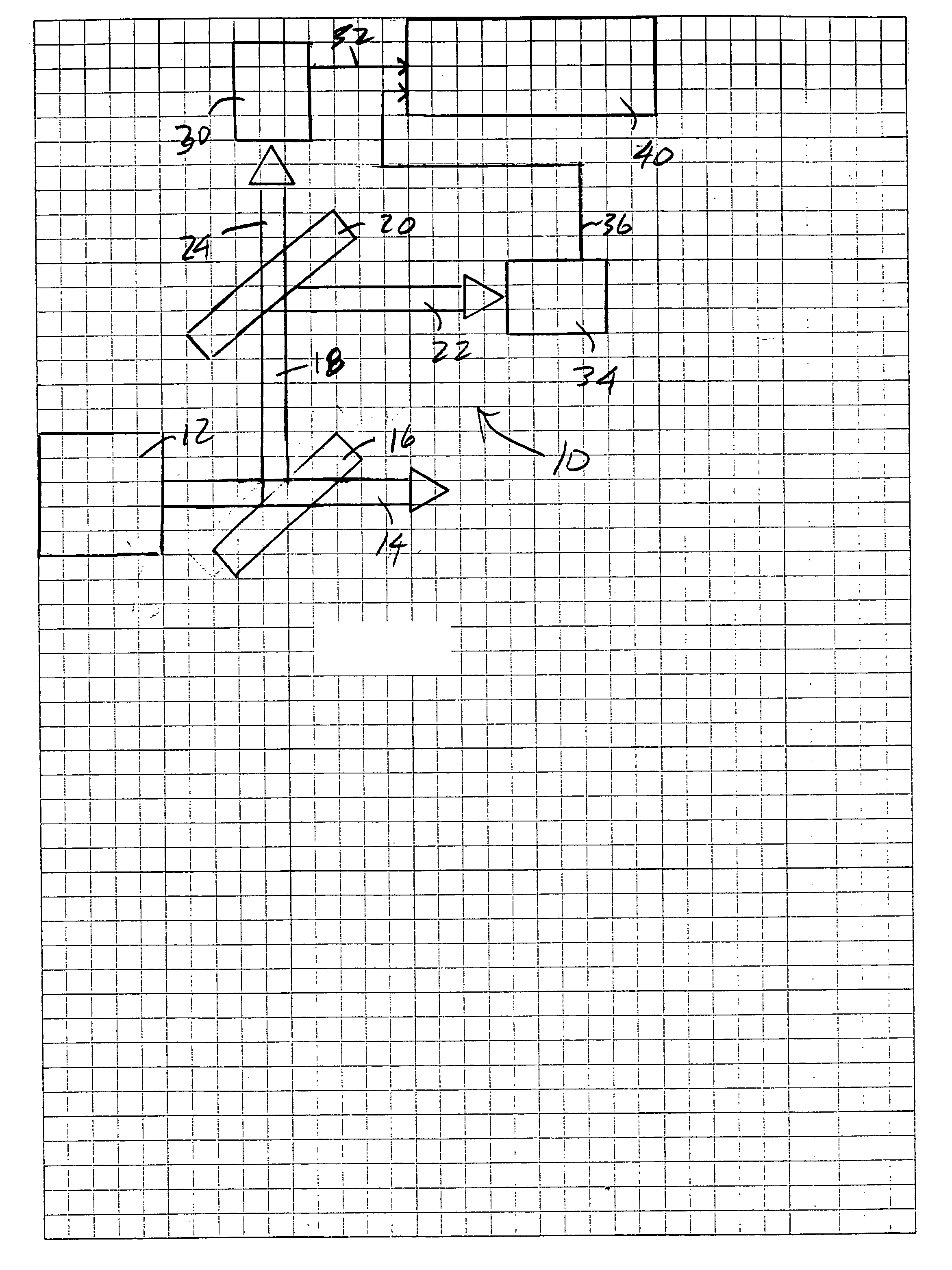
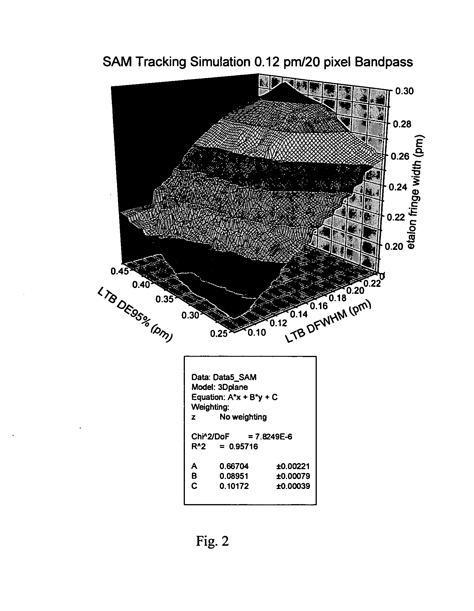
It is the purpose of this invention to mitigate these and similar measurement errors by employing more than one spectrometer operating in parallel within a single bandwidth meter, where the multiple spectrometer sub-circuits have significantly different impulse response function bandwidths. Because each sub-circuit has a different bandpass, each sub-circuit has a correspondingly different relative sensitivity to energy content in various regions of the spectrum. For example, a fringe FWHM measurement of the output of a very narrow bandpass circuit will give a result that accurately approximates the FWHM of the source spectrum, but a fringe FWHM measurement of a very wide bandpass circuit will give a result that is more closely related to the total energy content of the source spectrum. By choosing the bandwidth of the impulse response functions of the sub-circuits carefully, it is possible to mitigate the errors described above and simultaneously provide accurate estimates of integral bandwidth metrics such as the E95 width using only simple algebraic equations. A significant advantage of the invention is that these simple equations can be handled with little computational overhead, important for real-time applications such as bandwidth monitoring or sensing in high-repetition-rate pulsed lasers.

Problems solved by technology

Further, the impulse response of the spectrometer may be similarly complex or unknown.
However, it is not always practical or even possible to obtain a spectrometer with such a narrow-bandwidth impulse response, particularly when it is required to be very narrow in comparison to a source such as a laser which itself may be extremely narrow (tens of femtometers or less on a wavelength scale).
As noted above, this is not necessarily a good approximation, and can fail or become very difficult to implement dependably for certain types of bandwidth metrics.
Calculation of integral bandwidth metrics such as E95% can be inaccurate or very computationally intensive using this technique.
However, because the ratio of the FWHM bandwidths of the source spectrum and impulse response function is close to unity, this method may lose accuracy in the event that the shape of the laser spectrum deviates too far from an approximately-Lorentzian shape.
For example, a narrowing of the central spectral peak of the source spectrum with a concomitant increase in energy in the near wings can result in an over-estimation of the FWHM bandwidth in this approximation.
However, if the shape of the laser spectrum changes with operating conditions, with system alignment, or over the lifetime of the product, even this compensation will not remain accurate.
Also at issues is the complicating possibility that in a manufacturing setting, the etalon spectrometer may be tested and offset-calibrated on one laser, but is ultimately be installed on another that has a slightly different spectral shape.
In this case the calibration may be in error.

Method used


Image

  • Optical bandwidth meter for laser light
  • Optical bandwidth meter for laser light
  • Optical bandwidth meter for laser light

Examples


Embodiment Construction

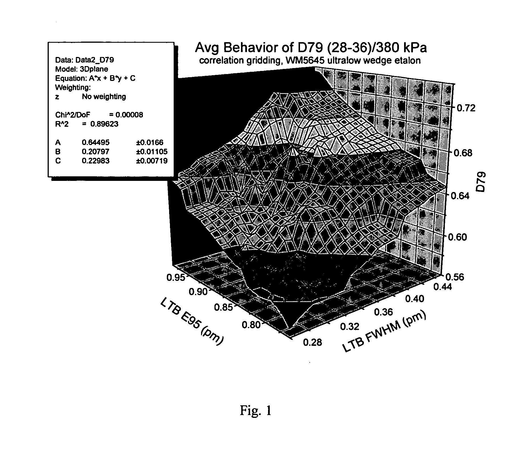
Turning now to FIG. 1 three is shown a three-dimensional plot of the response of a bandwidth meter employing, e.g., an etalon spectrometer, e.g., an etalon manufactured by Coherent, Inc., as the values of FWHM and E95 are varied as measured utilizing a very accurate spectrometer, e.g., a grating spectrometer, e.g. ELIAS-I as manufactured by Laser Technik Berlin (“LTB”).

It can bee seen that the etalon spectrometer response is comparably influenced by changes in both E95 and to FWHM of the source (a line-narrowed discharge-pumped excimer laser) over the operating range. All units are in pico-meters. A least-squares fit to a plane model of the data yields the approximation (etalon fringe width)=A*(source FWHM)+B*(source E95)+C with A=0.64495±0.0166, and B=0.20797±0.01105 and C=0.22983±0.00719. In the prior art this response has been modeled in a simpler form, in some cases where A is set identically equal to one and B is set identically equal to zero, and all of the modeling is done...


PUM


Abstract

A method and apparatus for measuring bandwidth of light emitted from a laser is disclosed which may comprise: a first and second wavelength sensitive optical bandwidth detectors providing, respectively, an output representative of a first parameter indicative of the bandwidth of the emitted light as measured respectively by the first and second bandwidth detectors, and an actual bandwidth calculation apparatus adapted to utilize these two outputs as part of a multivariable linear equation employing predetermined calibration variables specific to either the first or the second bandwidth detector, to calculate a first actual bandwidth parameter or a second actual bandwidth parameter. The first actual bandwidth parameter may be a spectrum full width at some percent of the maximum (“FWXM”), and the second actual bandwidth parameter may be a portion containing some percentage of the energy (“EX”). The first and second bandwidth detectors may an etalon and the outputs may be representative of a fringe width of a fringe of an optical output of the respective etalon at FWXM. The precomputed calibration variables may be derived from respective three dimensional plots representing, respectively, detector outputs in relation to a calibrating input light with known values of the first and second actual bandwidth parameters, which may be FWXM and EX. The first / second three dimensional plot may provide a solution: (first / second output)=(a / d*(calibrating input light known value of FWXM))+(b / e*(calibrating input light known value of EX)+c / f; and the actual bandwidth calculation apparatus may use the derived equation: (first actual bandwidth parameter)=((b*(second output))−(e*(first output))+ce−bf) / (bd−ae), or the equation: (second actual bandwidth parameter)=((a*(second output))−(d*(first output))+cd−af) / (ae−bd). FWXM may be FWHM and EX may be E95. The transfer function of the first optical bandwidth detector may be selected to be much more sensitive to FWXM than to EX and the transfer function of the second optical bandwidth detector may be selected to be much more sensitive to EX than to FWXM.

Description

RELATED APPLICATION This application is related to an application entitled METHOD AND APPARATUS FOR MEASURING BANDWIDTH OF AN OPTICAL OUTPUT OF A LASER assigned to the assignee of the present application and previously filed (Attorney Docket No. 2003-0056-01), the disclosure of which is hereby incorporated by reference. FIELD OF THE INVENTION The present invention relates to the determination of the spectral bandwidth of a laser. More generally the present invention relates to the accurate estimation of the bandwidth of an optical source using interferometric or dispersive instruments (“spectrometers”) whose impulse response functions have bandwidth generally comparable to or larger than that of the source being measured. BACKGROUND OF THE INVENTION Spectrometers based on dispersive optical elements or optical interference phenomena are well-known instruments commonly applied for the measurement of the absolute wavelength and bandwidth of light sources. When employed as a bandwid...

Claims


Application Information

Patent Timeline
IPC IPC(8): G01J1/42G01J3/02G01J3/28G01J3/45
CPCG01J1/0228G01J1/4257G01J3/45G01J3/027G01J3/28G01J3/02
Inventor RAFAC, ROBERT J.
Owner CYMER INC
Learn More