
Calculating device and flow meter equipped with calculating device

a calculation device and flow meter technology, applied in computing, measurement devices, instruments, etc., can solve the problems of affecting the amplitude of ultrasonic waves, the error between the value calculated using interpolation and the value that should actually be calculated, and the noise of measured propagation times, so as to reduce the processing time of the calculation device, and the computational overhead is small.

Inactive Publication Date: 2013-07-30
YAMATAKE HONEYWELL CO LTD
View PDF7 Cites 4 Cited by
  • Summary
  • Abstract
  • Description
  • Claims
  • Application Information

AI Technical Summary

Benefits of technology

The patent describes a device that calculates the difference in time between two signals in a flow meter by performing a Fourier transform and an inverse Fourier transform. This device has a minimal computational load, reducing processing time and allowing for a more cost-effective structure. The technical effect of this patent is to provide a reliable and efficient tool for calculating the difference in propagation times between signals in a flow meter.

Problems solved by technology

On the other hand, the ultrasonic waves used in ultrasonic flow meters have frequencies in the order of tens of kilohertz through 1 MHz, and thus the period of the signals is in excess of 1 μs, and thus the measured propagation times are susceptible to the influence of noise.
However, the amplitude of the ultrasonic waves is affected by the speed of flow and state of flow of the medium within the flow path.
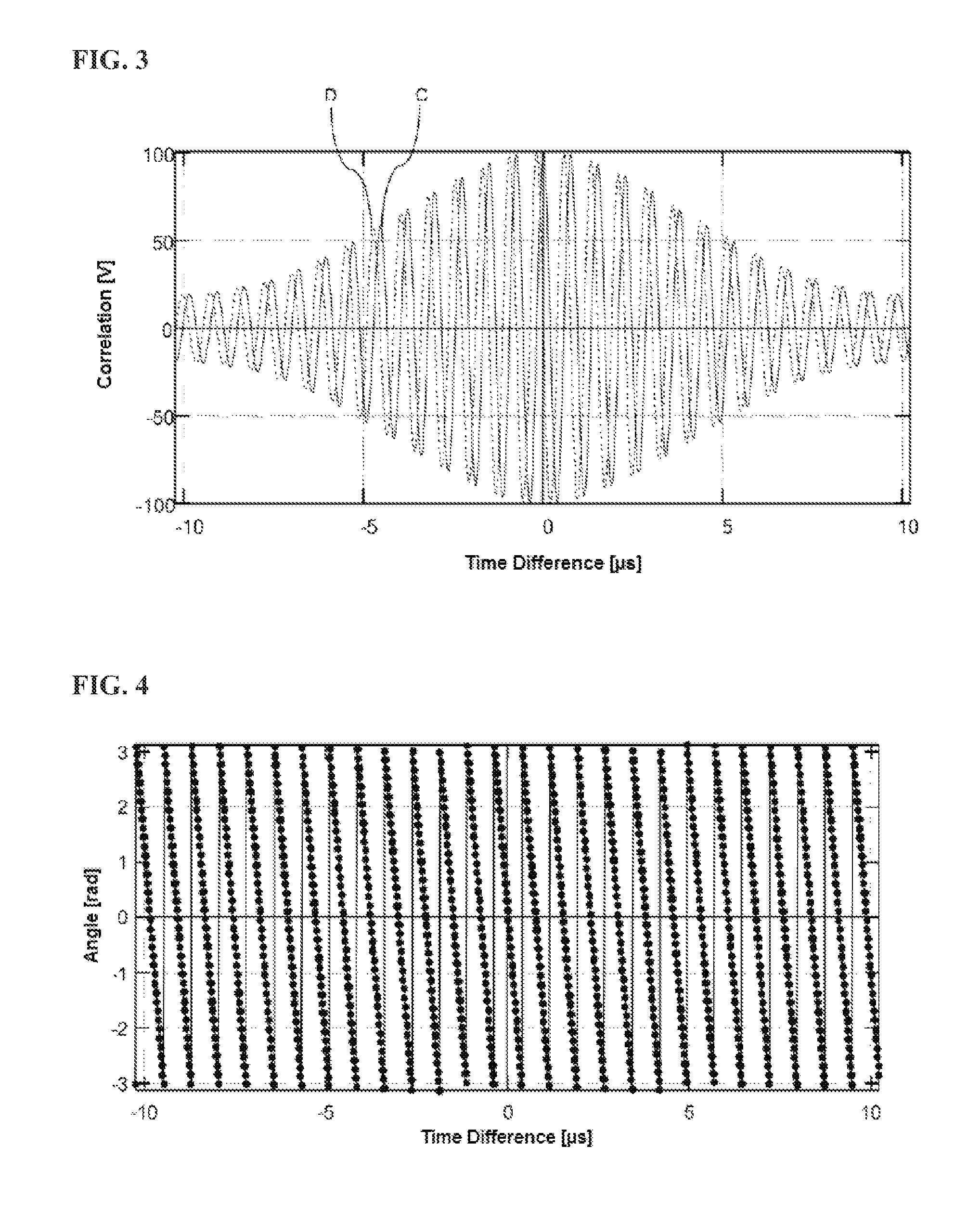
However, even when interpolating using a quadratic function, still there will be error between the value calculated using interpolation and the value that should actually be calculated.
As mentioned previously, it is necessary to have a resolution in the order of nanoseconds or sub-nanoseconds in the difference between propagation times, so an error of 400 ps will negatively affect the measurement results.
On the other hand, if a higher-order correlation were used for the interpolation, the interpolation formula would become complex, and would not be practical.
However, this structure has a problem in that the computational overhead is too great.

Method used


Image

  • Calculating device and flow meter equipped with calculating device
  • Calculating device and flow meter equipped with calculating device
  • Calculating device and flow meter equipped with calculating device

Examples


Embodiment Construction

[0031]One form of example according to the present invention is explained in detail following the structure below while referencing the drawings. Note that the form of embodiment that is explained below is no more than one example of the present invention, and the scope of technology of the present invention is not limited thereto. Note that in each of the drawings, identical components are assigned identical codes, and in some cases explanations thereof may be omitted.

1. DEFINITIONS

[0032]First terminology used in the present specification is defined as follows.

[0033]“XX portion”: While this includes components that are structured from electrical circuits, and the like, there is no limitation thereto, and this also includes physical means for achieving the function of the portion, functional means that are achieved through software, and the like. Furthermore, a function of a single component may be achieved through two or more physical or functional means, and functions of two or mo...


PUM


Abstract

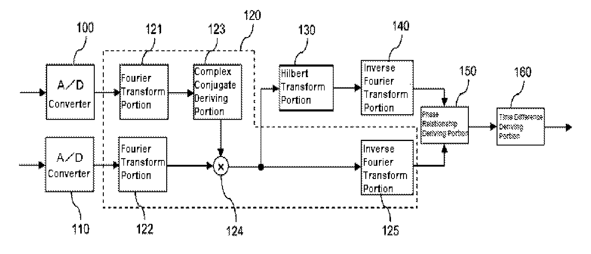
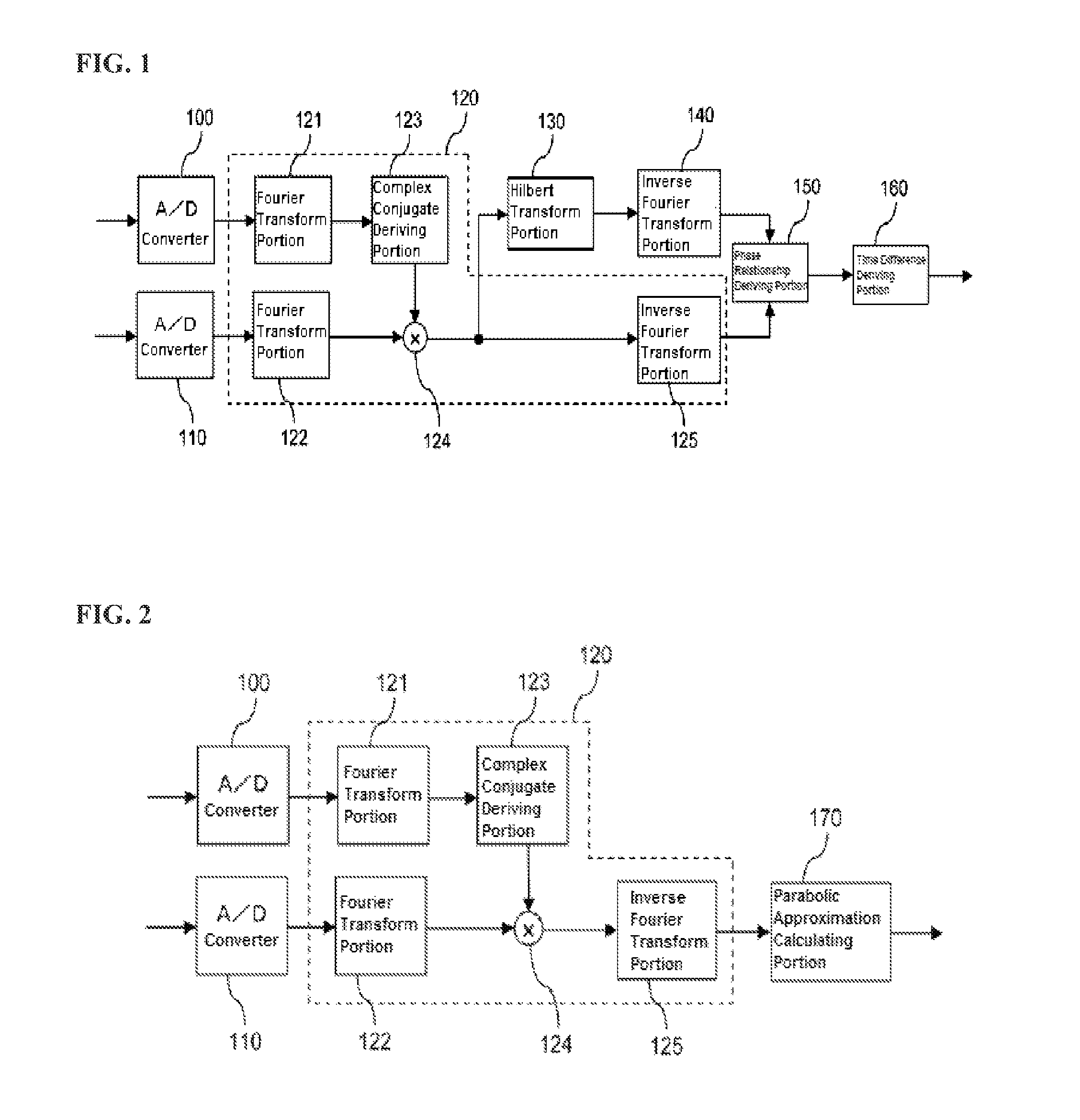
The calculating device has first and second Fourier transform portions performing Fourier transforms on two respective inputted signals; a complex conjugate deriving portion deriving a complex conjugate of a value outputted from the first Fourier transform portion; a multiplier multiplying the complex conjugate with the value outputted from the second Fourier transform portion, and outputting the value after the multiplication; a Hilbert transform portion performing a Hilbert transform on the value after multiplication; first and second inverse Fourier transform portions performing respective inverse Fourier transforms on the value after multiplication and the value outputted from the Hilbert transform portion; a phase relationship deriving portion deriving a phase relationship between the two inputted signals based on the values outputted from the first and second inverse Fourier transform portions; and a time difference deriving portion deriving a time difference between the two inputted signals based on the phase relationship.

Description

CROSS REFERENCE TO RELATED APPLICATIONS[0001]The present application claims priority under 35 U.S.C. §119 to Japanese Patent Application No. 2010-046682, filed Mar. 3, 2010, which is incorporated herein by reference.FIELD OF TECHNOLOGY[0002]The present invention relates to a calculating device used as, for example, a portion of a structure of a flow meter, and relates to, for example, a calculating device able to derive a time difference between a first inputted signal and a second inputted signal that has a delay relative to the first inputted signal.BACKGROUND OF THE INVENTION[0003]As one flow meter there is an ultrasonic flow meter that uses the difference in propagation times produced when an ultrasonic wave propagates within a medium. As illustrated in FIG. 10, for example, the ultrasonic flow meter has ultrasonic transceivers 10 and 11 disposed in a flow path, and measures the speed of flow of a medium, such as a gas or a liquid, that flows in the flow path, based on the diffe...

Claims


Application Information

Patent Timeline
Patent Type & Authority Patents(United States)
IPC IPC(8): G06F19/00G01F1/00
CPCG06F19/00G01F1/00G16Z99/00G01F1/667G01F1/66
Inventor SASAKI, HIROSHI
Owner YAMATAKE HONEYWELL CO LTD
Learn More