
Fluid flow properties from acoustically stimulated NMR

Active Publication Date: 2005-01-13
EXXON RES & ENG CO
View PDF12 Cites 23 Cited by
  • Summary
  • Abstract
  • Description
  • Claims
  • Application Information

AI Technical Summary

Problems solved by technology

The disadvantage of this method is its high cost and that the flow parameters are only obtained over small reservoir intervals.
This procedure is costly and reservoir flow parameters are only determined for selected reservoir intervals where cores from which cores are cut.
There is also an additional uncertainty introduced on the measured flow parameters because of the possibility that the fluids redistribute in the pore space when the core is removed from the reservoir.
The major disadvantage is that the fluid flow properties of the reservoir are inferred from measurements on non-flowing fluids, rather than measured directly on fluid flowing in the rock.
This large number of fit parameters has the consequence of introducing large uncertainties in the estimation of the permeability.
The major disadvantage of all continuous log wire line tools is that the fluid permeability is not directly measured but is inferred from other petrophysical properties of the reservoir rock.
A major complication is that the attenuation is determined by the bulk properties, which includes both the grain and fluid properties.
A major complication in this measurement is that the conductivity varies with salinity as well as the relative saturation of hydrocarbons and also depends on the amount and types of clays and minerals present.
However this relationship is complex and the NMR relaxation time spectrum can only be converted to a pore size distribution in ideal circumstances when all relevant parameters such as the surface relaxivity and contributions of the pore-to-pore coupling are known.
As a result of the complications in the interpretation of each of these measurements, the permeability inferred from the data analysis is bounded by large uncertainties.

Method used


Image

  • Fluid flow properties from acoustically stimulated NMR
  • Fluid flow properties from acoustically stimulated NMR
  • Fluid flow properties from acoustically stimulated NMR

Examples


Embodiment Construction

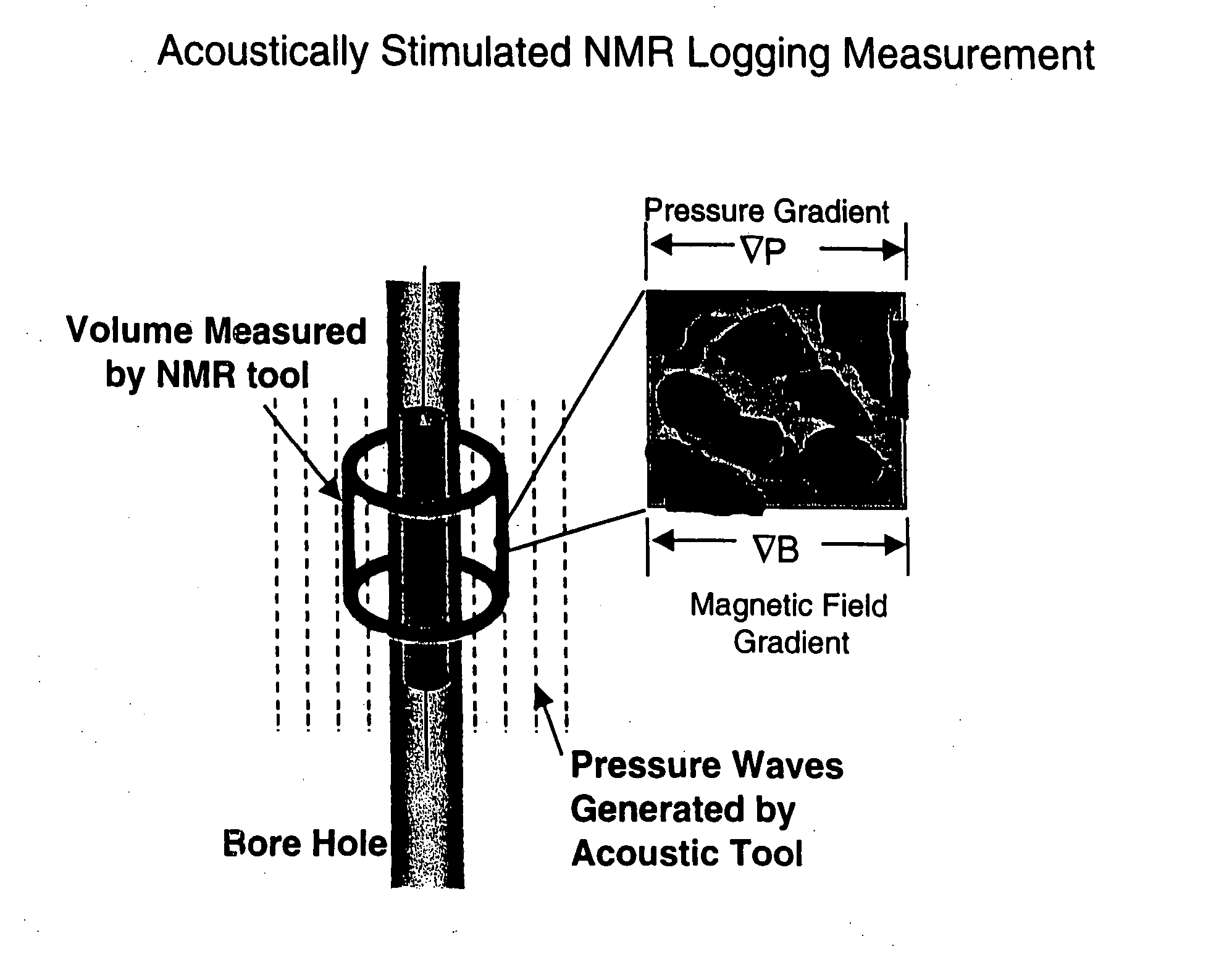
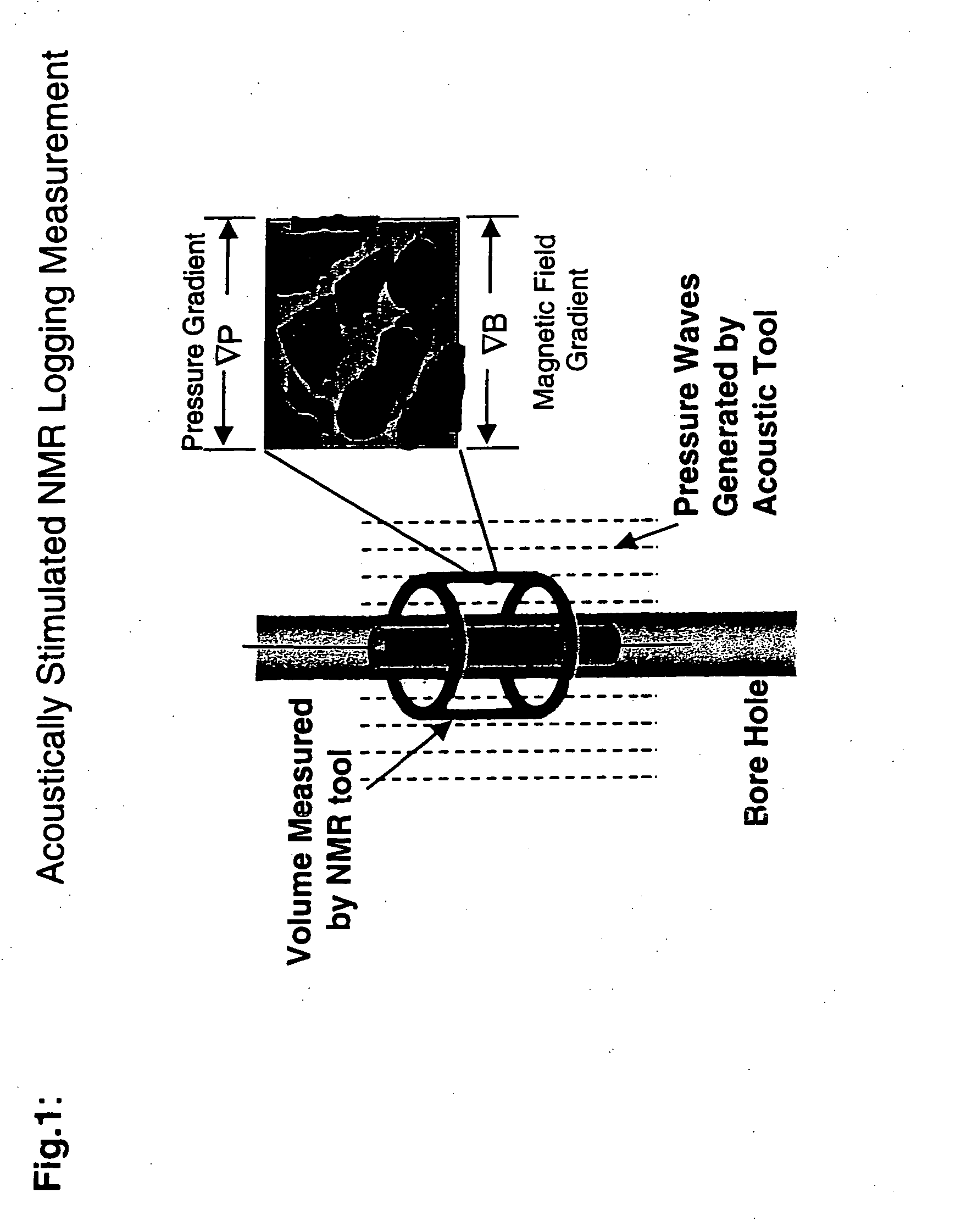
The invention disclosed here describes methods that determine formation permeability by measuring NMR signals that respond to pressure gradients created in the bore hole. These pressure gradients create motion of fluids in the rock pore space of the rocks in the formation surrounding the bore hole. In the case of hydraulic contact between the fluid in the borehole and the fluid in the formation rock, the displacement of the fluid in the borehole creates the displacement of the fluid in the formation rock. This is frequently referred to as the squirt boundary condition.

Motion of the fluid in the formation rock can also be created when there is no direct hydraulic contact between the fluid in the borehole and the fluid in the formation rock. Hydraulic contact between these fluids can be broken by the presence of an impermeable barrier at the bore hole wall. This can for example be created by the deposition of drilling mud on to the bore hole wall or damage to the rock structure nea...


PUM


Abstract

This invention is a method to measure fluid flow properties of a porous medium, including, but not limited to, the fluid flow permeability. In a preferred embodiment, the measurements are made down hole in drill wells exploring for hydrocarbons or acquifers. The measurement involves two types of instruments. One instrument creates a pressure wave in the porous medium, which generates motion of the fluid in the pore space. The second instrument measures the fluid motion in the pore space using Nuclear Magnetic Resonance (NMR) methods. Any type of instrument that can generate a pressure gradient is suitable, including instruments that are remote from the NMR instrument. Magnetic field gradients can be used to localize the NMR signal to a specific region within the porous medium. The magnetic field gradient also provides the method by which the fluid motion is encoded on to the NMR signal. The permeability is calculated from the known pressure gradient present in the porous medium by virtue of the applied pressure gradient or pressure wave and the velocity of the fluid in the rock pore space as measured by NMR.

Description

BACKGROUND OF THE INVENTION One of the major objectives of open hole logging in hydrocarbon exploration wells is to evaluate the fluid flow properties of the reservoir. Flow properties of particular interest include the relative fluid saturation at a given capillary pressure, the fluid flow permeability, the fluid viscosities, and the volume of bound formation water. The capillary bound water saturation determines the volume fraction of water in the pore space that will flow from the rock. This volume fraction subtracted from the total rock pore volume provides a measure of the maximum producible oil volume. The fluid flow permeability indicates how fast the fluid will flow through the rock for a given pressure gradient. These fluid flow properties are required to determine the economics of the reserve and for field development planning, such as the number of wells, well spacing, surface facilities, pipeline facilities, etc, which will be needed for production. At present three me...

Claims


Application Information

Patent Timeline
IPC IPC(8): G01R33/44G01V3/32
CPCG01V3/32G01N24/081
Inventor THOMANN, HANSZHOU, MINYAO
Owner EXXON RES & ENG CO
Learn More