
Organometal complex, electroluminescence material using the complex, and electroluminescence element using the complex

a technology of complexes and organometals, applied in the field of organometal complexes, can solve the problems of increasing the cost of the material itself, poor heat resistance, and small number of usable ligands, and achieves high efficiency of the electroluminescence element, significant effect, and high coordination ability

Active Publication Date: 2005-01-13
SEMICON ENERGY LAB CO LTD
View PDF4 Cites 18 Cited by
  • Summary
  • Abstract
  • Description
  • Claims
  • Application Information

AI Technical Summary

Benefits of technology

The present invention provides a new type of organometal complex that can be easily synthesized and has a unique structure. These complexes can be used as sensitizers or in electroluminescence elements, and they have high light emission efficiency. The use of these complexes as illuminants can realize low power consumption. The invention also provides a method for synthesizing the ligand used in the organometal complex. The technical effects of this invention are the improved efficiency and cost-effectiveness of organometal complexes and their use in electroluminescence elements.

Problems solved by technology

However, since the ground state of ordinary organic compounds is a singlet state, the photoexcitation to the triplet excitation state results in a forbidden transition, and the triplet excitation molecule is hardly generated (a singlet excitation molecule is ordinarily generated).
However, almost all of the ligands are limited to those capable of forming a five-membered ring with the central metal, and, under the current situation, a desired light emission color is selected among the ligands.
That is to say, there is a problem that the number of usable ligands is still small.
Also, many of the ligands are difficult to synthesize or require a large number of steps for the synthesis, thereby leading to an increase in cost of the material itself.
Therefore, the poor heat resistance is problematic in the application thereof to an electronic device such as the electroluminescence element.

Method used


Image

  • Organometal complex, electroluminescence material using the complex, and electroluminescence element using the complex
  • Organometal complex, electroluminescence material using the complex, and electroluminescence element using the complex
  • Organometal complex, electroluminescence material using the complex, and electroluminescence element using the complex

Examples


embodiment mode 1

[Embodiment Mode 1]

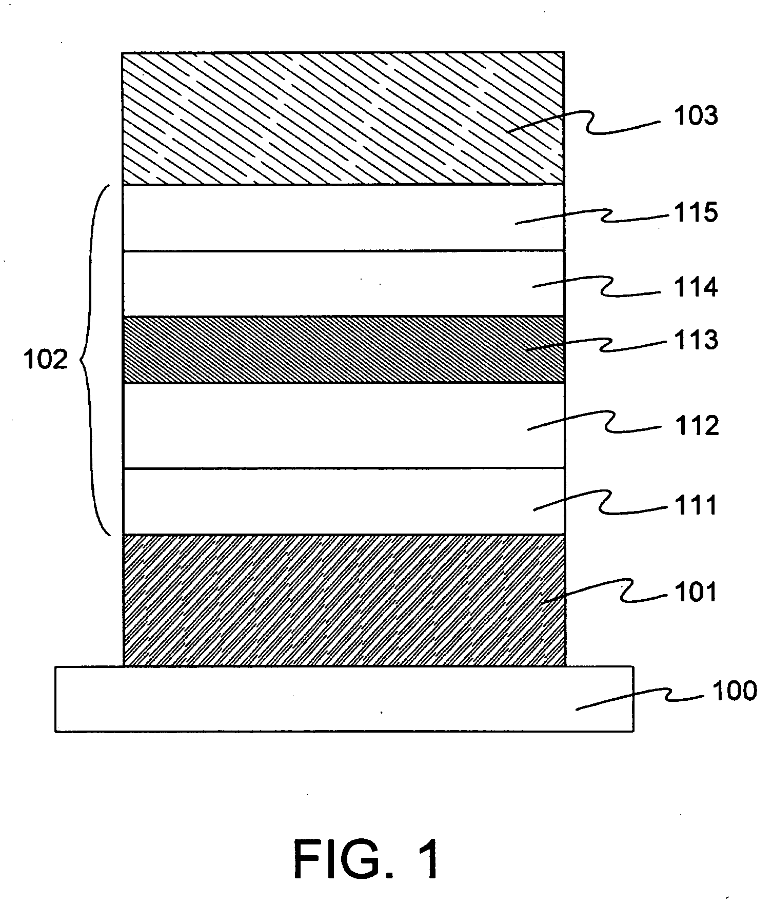
In this Embodiment Mode 1, an element structure of an electroluminescence element having a luminescent layer containing the organometal complex of this invention, a hole injection layer formed from a low-molecular material, a hole transport layer, a hole blocking layer, and an electron transport layer will be described with reference to FIG. 1.

Referring to FIG. 1, the structure is such that a first electrode 101 is formed on a substrate 100, and an electroluminescence layer 102 and a second electrode 103 are formed on the first electrode 101 in this order.

A material to be used for the substrate 100 is not limited so far as it has been used for conventional electroluminescence elements, and examples thereof are glass, quartz, a transparent plastic, and the like.

In this Embodiment Mode 1, the first electrode 101 functions as an anode, and the second electrode 103 functions as a cathode.

That is, the first electrode 101 is formed from an anode material, and t...

embodiment mode 2

[Embodiment Mode 2]

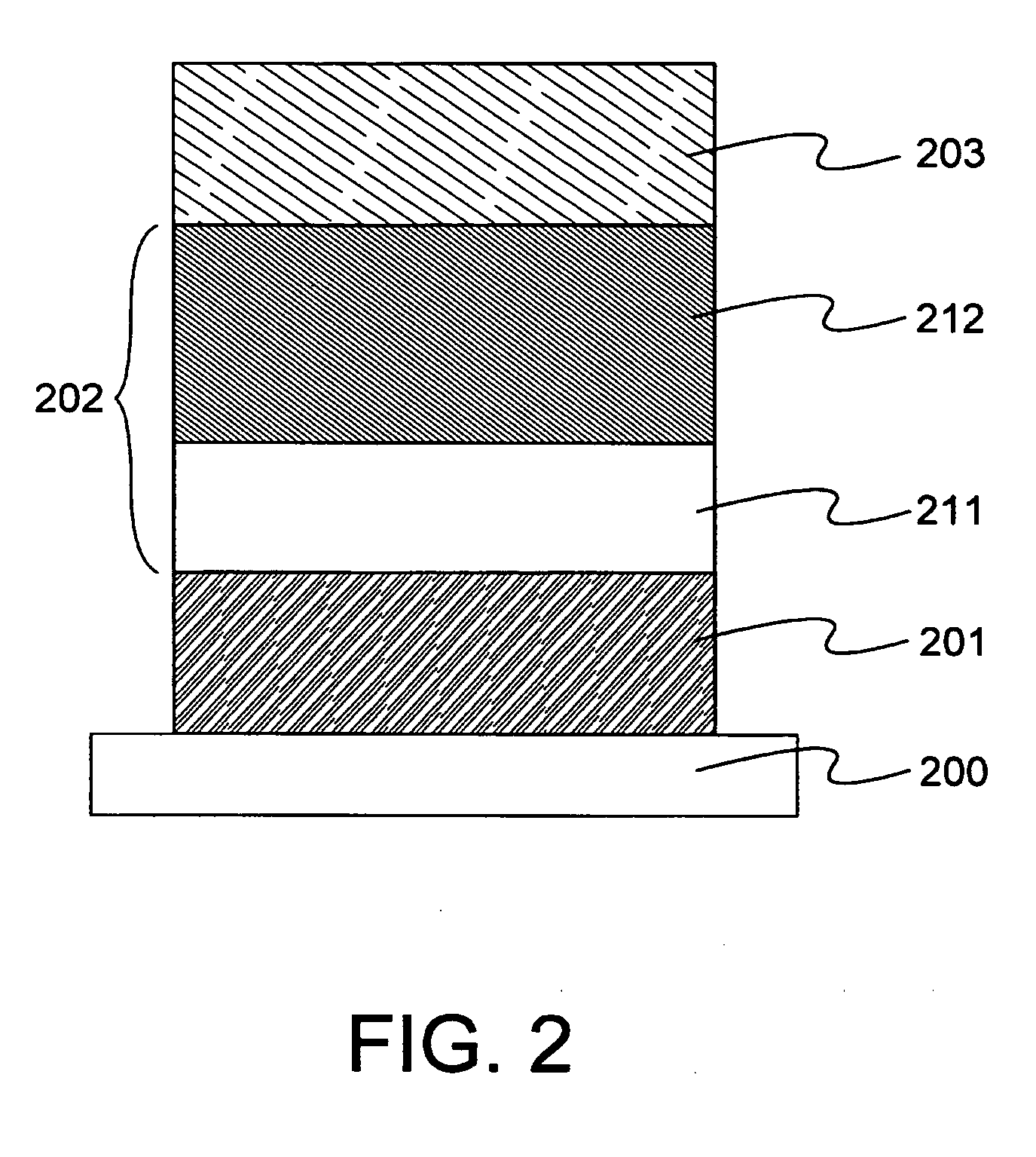
In this Embodiment Mode 2, an element structure of an electroluminescence element having a luminescent layer containing the organometal complex of this invention and a hole injection layer formed from a high-molecular material both of which layers are formed by wet processing will be described with reference to FIG. 2.

Since a substrate 200, a first electrode 201, and a second electrode 203 are formed by using the materials described in Embodiment Mode 1 and in the same manner as in Embodiment Mode 1, and then descriptions thereof are omitted.

An electroluminescence layer 202 is formed by stacking a hole injection layer 211 and a luminescent layer 212 in this Embodiment Mode 2.

As a hole injection material to be used for forming the hole injection layer 211, polyethylenedioxythiophene (abbreviation: PEDOT) which is doped with polystyrene sulfonic acid (abbreviation: PSS), polyaniline (abbreviation: PAni) doped with an accepter such as tetracyanoquinodimethane ...

embodiment mode 3

[Embodiment Mode 3]

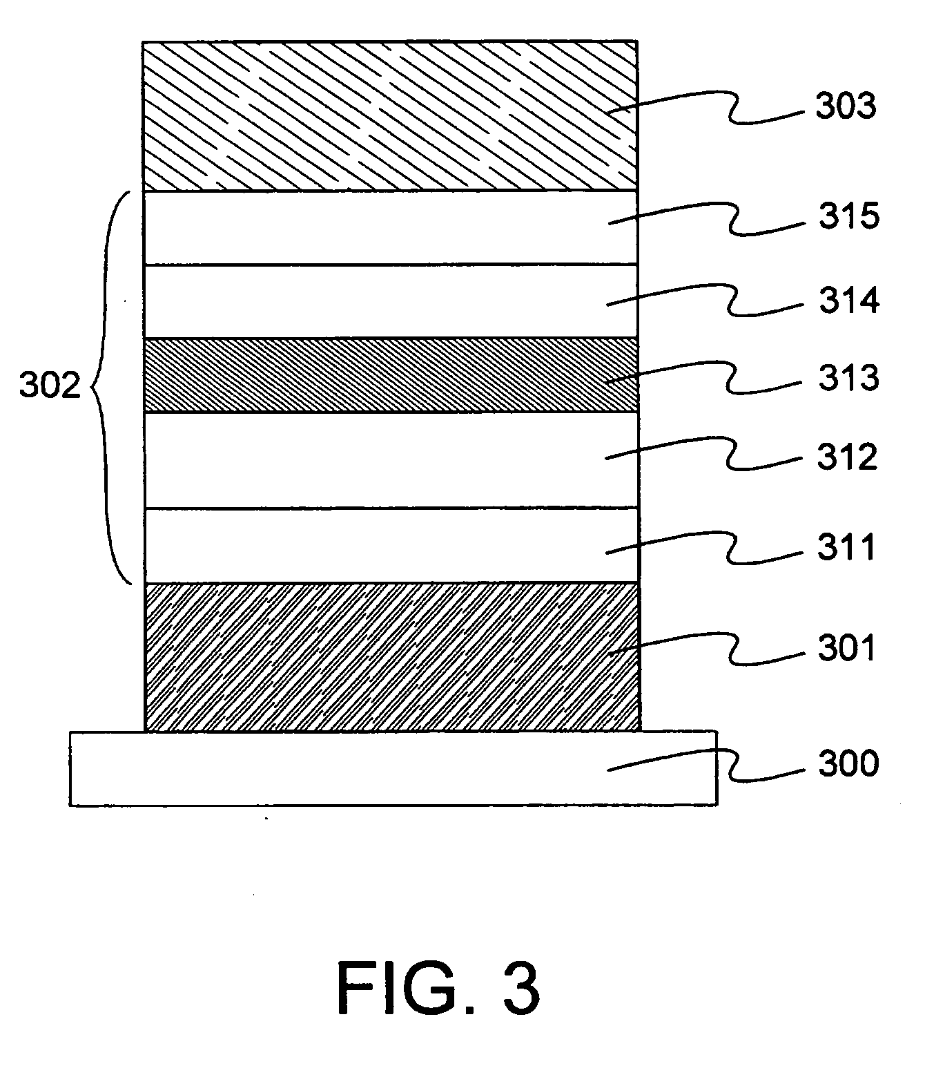
In this Embodiment Mode 3, an element structure of an electroluminescence element having a luminescent layer containing two types of guest materials which are the organometal complex of this invention and a fluorescent compound, a hole injection layer formed from a low-molecular material, a hole transport layer, a hole blocking layer, and an electron transport layer will be described with reference to FIG. 3.

Since it is possible to form a substrate 300, a first electrode 301, a second electrode 303, a hole injection layer 311, a hole transport layer 312, a hole blocking layer 314, and an electron transport layer 315 by using the materials described in Embodiment Mode 1 and in the same manner as described in Embodiment Mode 1, and then descriptions thereof are omitted.

In this Embodiment Mode 3, an electroluminescence layer 302 is formed by stacking the hole injection layer 311, the hole transport layer 312, a luminescent layer 313, the hole blocking layer 314,...


PUM

PropertyMeasurementUnit
internal quantum efficiencyaaaaaaaaaa
work functionaaaaaaaaaa

Abstract

An object of the present invention is to provide novel organometal complexes which is obtainable with a good yield by using a ligand which can be easily synthesized. Particularly, it is intended to provide the organometal complexes which is excellent in heat resistance. Further, it is intended to provide an electroluminescence element having high light emission efficiency by manufacturing the electroluminescence element using the organometal complex. Therefore, the organometal complex represented by the general formula (1) is synthesized. Further, this is applied to the electroluminescence element.

Description

TECHNICAL FIELD The present invention relates to novel organometal complexes. Particularly, this invention relates to the organometal complexes each of which is capable of converting a triplet excitation state into light emission. Also, this invention relates to an electroluminescence material using the organometal complex. Further, this invention relates to an electroluminescence element which has an anode, a cathode, and a layer (hereinafter referred to as electroluminescence layer) containing an organic compound capable of achieving light emission upon application of electric field and is formed by using the organometal complex. BACKGROUND ART Organic compounds (organic molecules) are brought into a state having energy (excitation state) by absorbing light. By going through this excitation state, various reactions (photochemical reactions) are caused in some cases, while luminescence is generated in other cases; therefore, the organic compounds have found various applications. ...

Claims


Application Information

Patent Timeline
Patent Type & Authority Applications(United States)
IPC IPC(8): C07D213/74C07F15/00
CPCC07D213/74C07D413/04Y10S428/917C07F15/0033C07D417/04C07F15/00C09K11/06C09K2211/1033C09K2211/1037C09K2211/185H10K85/342H10K50/11H10K2101/10
Inventor SEO, SATOSHIINOUE, HIDEKOTOKUDA, ATSUSHI
Owner SEMICON ENERGY LAB CO LTD
Learn More