
Hydraulic annular washing column, and process for separating solids from a suspension

a technology of annular washing and suspension, which is applied in the direction of gravity filter, feed/discharge of sedimentation settling tank, gravity filter, etc., can solve the problems of deformation or damage of crystals, difficulty in developing a column based on this principle suitable for large-scale commercial operation, and difficulty in homogeneous wash/separation front, etc., to facilitate homogeneous build-up of the bed and uniform/even wash front

Inactive Publication Date: 2005-01-13
NIRO PROCESS TECH
View PDF8 Cites 7 Cited by
  • Summary
  • Abstract
  • Description
  • Claims
  • Application Information

AI Technical Summary

Benefits of technology

[0015] The invention is based on the insight, that by providing a centrally located inner cylinder provided with at least one filter in the wall of said cylinder, in combination with at least one filter in the wall of the outer column, it has been found possible to optimise the distance that the liquid has to travel to reach the filters, while at the same time preventing or at least reducing the problems inherent to the known columns.
[0028] In case multiple filters are present in a wall at different locations along the length of the column, it can be advantageous to control the flow through each filter independently. In such a case the highest filters can be used to create the bed.
[0029] With these measures, of course combined with a careful dimensional construction of the annular treatment zone, on the one hand a uniform removal of the liquid over the whole cross section of the zone is obtained, and on the other hand, also by the applied force on the suspension, an acceptable friction between the packed crystal bed and the filters and the walls of the inner cylinder and the outer column is obtained. Further, a homogeneous build-up of the bed is facilitated and a very homogeneous flow is obtained, resulting in a uniform / even wash front.
[0034] The use of continuous hydraulic transport of the bed diminishes a.o. deformation and damage of the crystals in the bed. The porosity of the crystal bed decreases in the direction of the filters and consequently also the force exercised by the liquid in axial direction of the bed. This force must be bigger than the opposing forces, mainly the friction and the back pressure of the wash liquid, if used. The force on the crystal bed is determined by the pressure drop of the liquid over the bed between the inlet of the suspension and the liquid removal through the filters. The pressure drop can be increased by extending the length of the bed or by increasing the flow rate of the liquid. If the suspension to be treated contains too little liquid to cause the desired pressure drop through the liquid on the crystal bed, a portion of the liquid passed through the filters can be recycled, as a result of which the pressure drop over the bed increases. In fact, this boils down to a decrease of the particle density of the suspension to be concentrated at the beginning of the concentration zone.

Problems solved by technology

A disadvantage of this hydraulic washing column resides therein, that it is very difficult to develop a column based on this principle suitable for large scale commercial operation.
More in particular, with column sizes of over about 75 cm diameter, problems may occur with respect to pressure build-up and homogeneity of the wash / separation front, depending, among others, on the nature of the solid material and / or the particle size and shape thereof.
This big force exercised on the concentrated suspension involves the compression of the packed bed, which can result in deforming or damaging the crystals.
The consequence thereof is a further increase in pressure drop and a decrease in throughput capacity of the column.
Further an increased energy consumption may be the consequence too.
A further disadvantage of this known apparatus is that a homogeneous flow of washing liquid through the crystal bed becomes more difficult with increasing column diameter.
This disturbing effect of the filters mounted in the wall on the liquid flow in the crystal bed increases with a larger column diameter and results in an uneven profile of the washing front.
It is well known, that the presence of tubes in a packed bed of solids leads to a disturbance thereof.
Further problems encountered with this construction are that a homogeneous distribution of the slurry over the entire cross-section of the column is difficult, leading to that it is difficult to create a homogeneous bed, and that is it difficult to perform an accurate measurement of the bed height.
Finally it is to be noted the tubes require very narrow dimensional tolerance and precise positioning, which aspects, together with the increased amounts of materials, make the column more expensive to construct.
Quite likely those are the reasons that up to now this column has never been demonstrated successfully on an industrial scale.

Method used


Image

  • Hydraulic annular washing column, and process for separating solids from a suspension
  • Hydraulic annular washing column, and process for separating solids from a suspension

Examples


Embodiment Construction

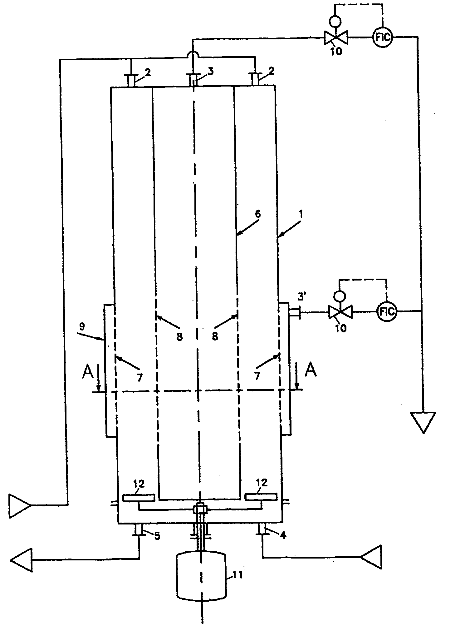
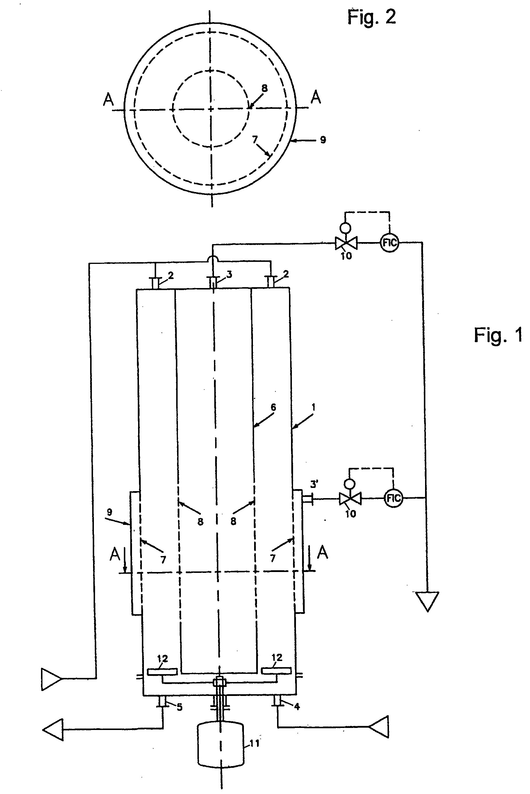
[0053] In FIG. 1, a hydraulic annular wash-column 1 is shown, having a suspension inlet 2, filtrate outlets 3 and 3′, a wash liquid inlet 4, and a product slurry outlet 5. Inside column 1, coaxially with the column a central cylinder 6 is positioned, which is closed at the lower end and is connected with the filtrate outlet 3.

[0054] Both in the outer wall of the column 1, and in the cylinder, filters 7 and 8 are present. Around the column a filtrate chamber 9 is present, provided with filtrate outlet 3′. Flow controllers 10 and 10′ are present in the lines from the filtrate outlets 3 and 3′ to regulate the filtrate flow.

[0055] A scraper device 12 is present at the bottom of the zone formed by the outer column wall 1 and the cylinder 6, which scraper 12 is driven by a scraper driver 11.

[0056]FIG. 2 shows a horizontal cross-section along line A-A of FIG. 1, wherein the numbers have the same meaning as in FIG. 1.

[0057] When operating the column according to FIG. 1, a suspension of ...


PUM

PropertyMeasurementUnit
Timeaaaaaaaaaa
Diameteraaaaaaaaaa
Distanceaaaaaaaaaa

Abstract

An apparatus for separating solids from a suspension includes a hollow cylindrical column having a central axis therethrough. The column has an interior with a cross-section, perpendicular to said axis, that is constant along said axis, and that extends from a first end to a second end of the column; one central tube axially disposed in said column and extending from said one end toward said opposite end, said central tube having an outer wall of constant diameter, said cylindrical column and said central tube defining an annular zone between them, extending axially from said first end of the column to at least near said second end of the column; at least one filter in said outer wall of the said central tube, forming the only direct communication between the said annular zone and the interior of the tube and at least one filter in the outer wall of said hollow cylindrical column; means for supplying a suspension to said first end of the column; means for removing suspension at said second end of the column; said interior defining a concentration zone means communicating with the interior of said central tube for removing liquid passed through said filter in said outer wall of the said central tube and means for removing liquid passed through the filter in the outer wall of said hollow cylindrical column; means acting on the liquid of said suspension for urging said liquid through said annular zone towards said filters.

Description

RELATED APPLICATIONS [0001] This is a Continuation of international application no. PCT / NL02 / 00598, filed 19 Sep. 2002, which designated the U.S., published in English as WO 03 / 024562 on 27 Mar. 2003, and whose contents are incorporated by reference.FIELD OF THE INVENTION [0002] The invention is directed to a hydraulic washing column for separating solids from suspensions. BACKGROUND OF THE INVENTION [0003] Separating solids from suspensions, optionally combined with washing of the solids in hydraulic washing columns is a well known technique for concentration of food products (coffee extract, juices), for recovering crystals in pure form from suspensions, for desalination of sea water, and the like. [0004] An apparatus for concentrating a suspension is known from U.S. Pat. No. 2,854,494. This patent describes a crystal wash column in which in a cylindrical room a crystal suspension is concentrated by directing this suspension along a section of the cylindrical wall which contains o...

Claims


Application Information

Patent Timeline
IPC IPC(8): B01D9/00B01D29/00B01D29/11
CPCB01D9/00B01D29/114B01D29/117B01D29/54B01D29/78
Inventor JANSENS, PIETER JOHANNESDE GRAAUW, JOHANNES
Owner NIRO PROCESS TECH
Learn More