
Multi-phase separation system

a multi-phase separation and separation system technology, applied in the direction of sedimentation settling tanks, settling tank feed/discharge, chemical/physical processes, etc., can solve the problems of volatile organic compounds, serious spillage problems, and contamination of ground water

Inactive Publication Date: 2005-01-13
LIQUID SEPARATION TECH & EQUIP
View PDF25 Cites 31 Cited by
  • Summary
  • Abstract
  • Description
  • Claims
  • Application Information

AI Technical Summary

Benefits of technology

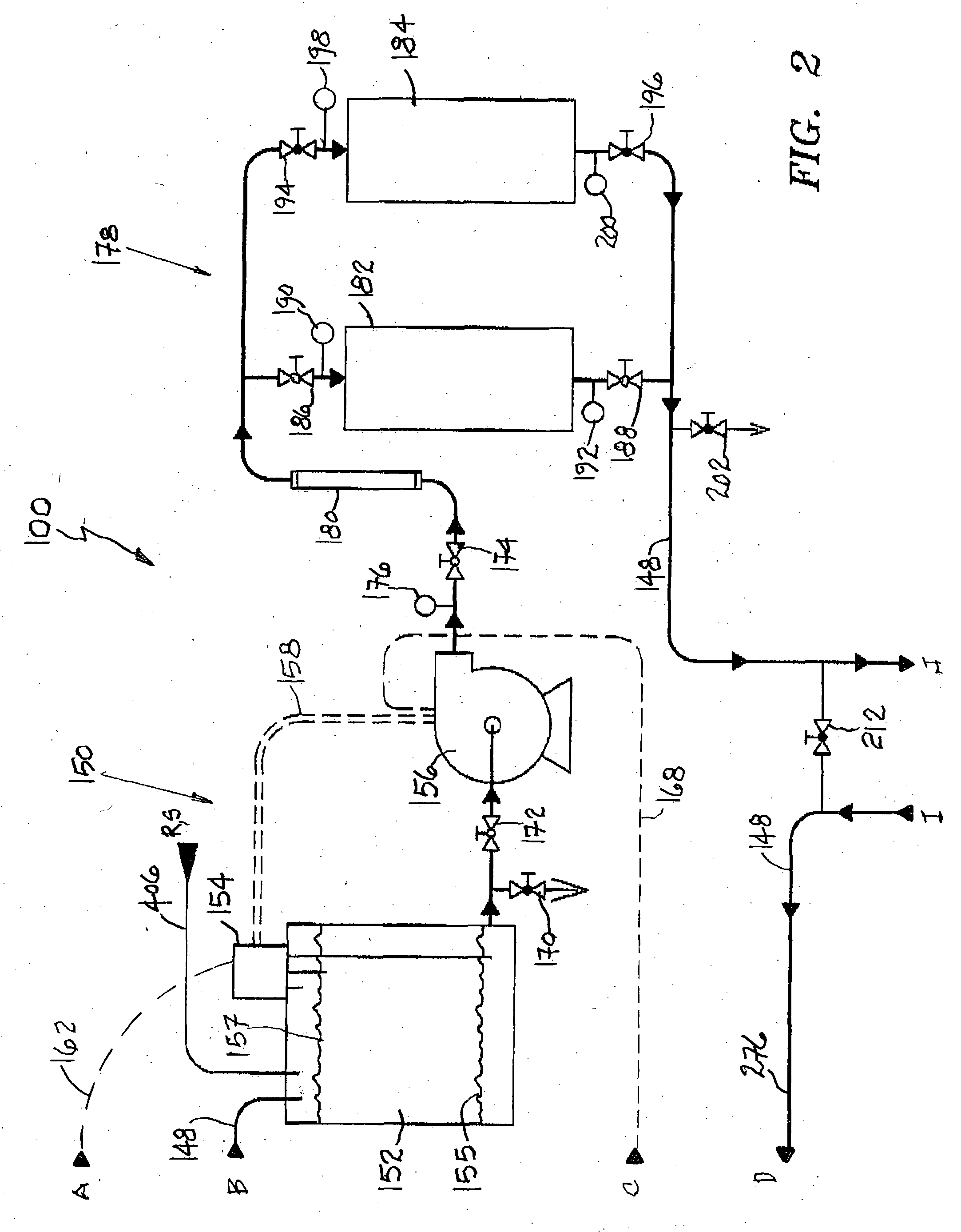
[0016] In a preferred embodiment, a pre-filtering and pre-separating module receives contaminated groundwater, separates contaminates not in solution, and filters out and collects oils and greases on a polypropylene screen. A primary flow control module includes a surge tank having a level control system employed to control a centrifugal pump which regulates the liquid flow throughout the entire system. A micron filtration bank module is employed for filtering out particles larger than 5-microns for eliminating sediment. A contaminant condenser module utilizes the cooler filtered fluid from the micron filtration bank module as a cooling medium to condense the contaminated gas phase emitted from a phase reaction chamber. A media temperature equalization module functions to equalize the temperature of the contaminated fluid from the contaminate condenser module with a source of carrier atmospheric air prior to entering the phase reaction chamber for minimizing the probability of collateral reactions occurring within the phase reaction chamber.

Problems solved by technology

In general, the ground water has become contaminated by the release of gasoline which includes the MTBE and VOC additives stored in underground tanks.
Since MTBE is a carcinogen and is highly “hydro-scopic”, i.e., it has a high affinity for water, spillage is a serious problem.
Likewise, a Volatile Organic Compound (hereinafter “VOC”) is considered hazardous to humans and can also be a carcinogen.

Method used


Image

  • Multi-phase separation system
  • Multi-phase separation system
  • Multi-phase separation system

Examples


Embodiment Construction

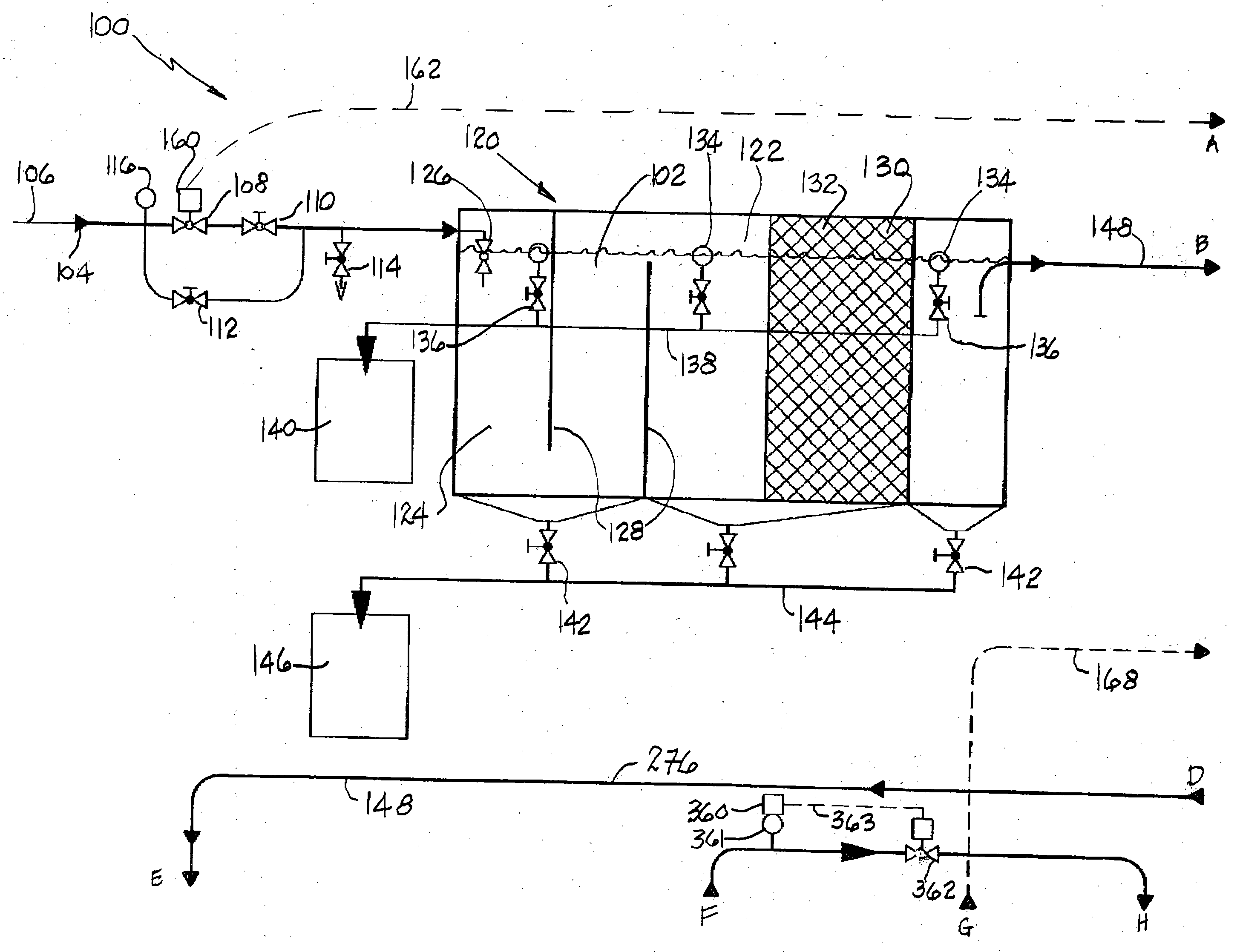
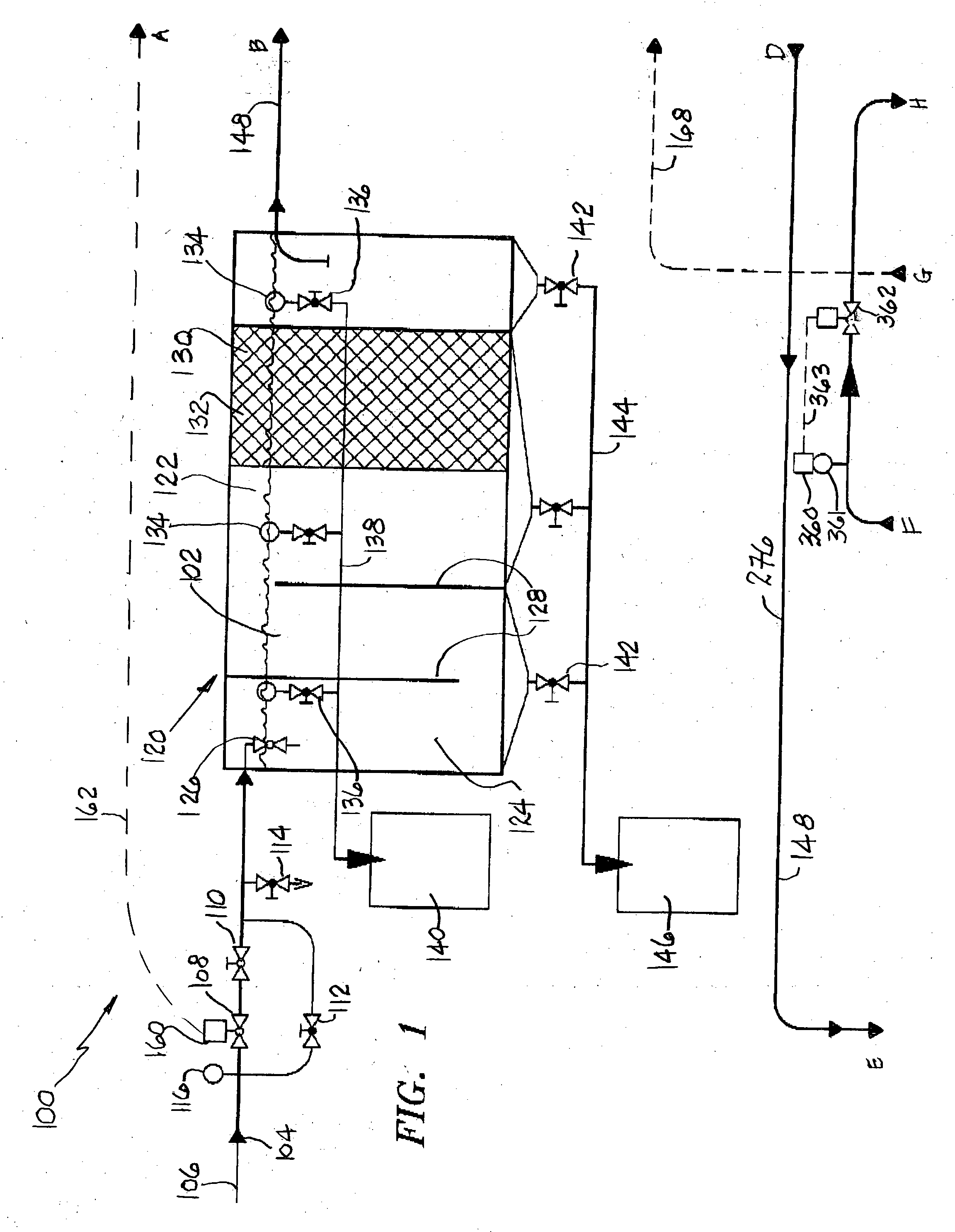
[0026] The present invention is a multi-phase separation system 100 typically utilized to remove chemical fuel additives such as Methyl Tertiary-Butyl Ether (hereinafter MTBE) and Volatile Organic Compounds (hereinafter VOC's) from fluids, such as groundwater 102 from a contaminated water source indicated by an arrow 104 in FIG. 1. The multi-phase separation system 100 can be used to decontaminate groundwater 102 after spillage or leakage of processed gasoline containing Methyl Tertiary-Butyl Ether (MTBE) from fuel storage tanks (not shown) and Volatile Organic Compounds (VOC's) also utilized in gasoline and in various industrial environments such as in the steel industry. The multi-phase separation system is designed to receive contaminated fluid such as ground water 102 and to discharge liquid meeting the Environmental Protection Agency (EPA) water quality requirements and thus suitable for human consumption and usage.

[0027] In general, the ground water 102 becomes contaminated b...


PUM

PropertyMeasurementUnit
Diameteraaaaaaaaaa
Temperatureaaaaaaaaaa
Flow rateaaaaaaaaaa

Abstract

A multi-phase separation system utilized to remove contaminants from fluids includes a pre-filtering module for filtering a contaminated fluid to provide a filtered contaminated fluid. A condenser module receives the filtered contaminated fluid and a contaminated gas phase for condensing the contaminated gas phase to a contaminated liquid. A phase reaction chamber converts the filtered contaminated fluid to a contaminated mist wherein the mist is subjected to a low energy, high vacuum environment for providing a first change of phase by separating into a contaminated gas phase and a liquid mist phase. The contaminated gas phase is carried out of the phase reaction chamber by a carrier air. A vacuum pump provides the low energy, high vacuum environment in the phase reaction chamber and delivers the contaminated gas phase to the condenser module for condensation providing a second change of phase.

Description

BACKGROUND OF THE INVENTION [0001] 1. Technical Field [0002] The present invention relates to the elimination of pollution from groundwater. More specifically, the present invention relates to methods and apparatus for a multi-phase separation system typically utilized to remove the chemical additives Methyl Tertiary-Butyl Ether (MTBE) and Volatile Organic Compounds (VOC's) from fluids such as groundwater. [0003] 2. Background Art [0004] The prior art is directed to methods and apparatus for removing chemical additives from fluids such as groundwater. [0005] Methyl Tertiary-Butyl Ether (hereinafter “MTBE”) is a synthetic organic chemical primarily utilized as a fuel additive or oxygenate and was initially blended in gasoline to increase octane ratings after the phase-out of lead and aromatics. Thus, MTBE was intended to (a) to enhance the combustion of gasoline by keeping fluids in solution within the gasoline so the fluids do not freeze and foul engine components, and (b) to reduce...

Claims


Application Information

Patent Timeline
IPC IPC(8): B01D1/16B01D1/30B01D3/10B01D5/00B01D21/00B01D45/02B01D53/00C02F1/00C02F1/04C02F1/20
CPCB01D1/16Y10S210/05B01D3/10B01D5/0006B01D5/0054B01D5/006B01D17/045B01D21/0012B01D45/02B01D53/002B01D2257/704B01D2257/708C02F1/001C02F1/04C02F1/20C02F2101/322C02F2103/06C02F2301/063B01D1/305B01D1/00B01D1/30B01D5/00
Inventor SPANI, WAYNE W.
Owner LIQUID SEPARATION TECH & EQUIP
Learn More