Gapped core structure for magnetic components

a core structure and magnetic component technology, applied in the direction of inductances, inductances with magnetic cores, basic electric elements, etc., can solve the problems of complex structure, difficult and costly, and insufficient bonding of cores, so as to improve manufacturability, increase the size of components, and increase efficiency

Inactive Publication Date: 2005-01-06
COOPER TECH CO
View PDF4 Cites 11 Cited by
  • Summary
  • Abstract
  • Description
  • Claims
  • Application Information

AI Technical Summary

Benefits of technology

[0011] It is therefore desirable to provide a magnetic component of increased efficiency and improved manufacturability for circuit board applications without increasing the size of the components and occupying an undue amount of space on a printed circuit board.

Problems solved by technology

It has been noted that in some applications the bonded cores are insufficiently bonded for their intended use, and controlling the epoxy to glass spheres ratio in the adhesive mix has proven very difficult.
Multiple (more than two) pieces of spacer material are rarely used, since the problem of securing the structure together becomes very complicated, difficult and costly.
Resistance of the conductor creates heat as the current circulates, which reduces the efficiency of the magnetic component.
Moving the conductor farther away from the magnetic flux lines can reduce the amount of energy that is coupled to the conductor and hence increase the efficiency of the component, but this typically entails increasing the size of the component, which is undesirable from a manufacturing perspective.
Separation of the components occupies valuable space on a printed circuit board.

Method used


Image

  • Gapped core structure for magnetic components
  • Gapped core structure for magnetic components
  • Gapped core structure for magnetic components

Examples


second embodiment

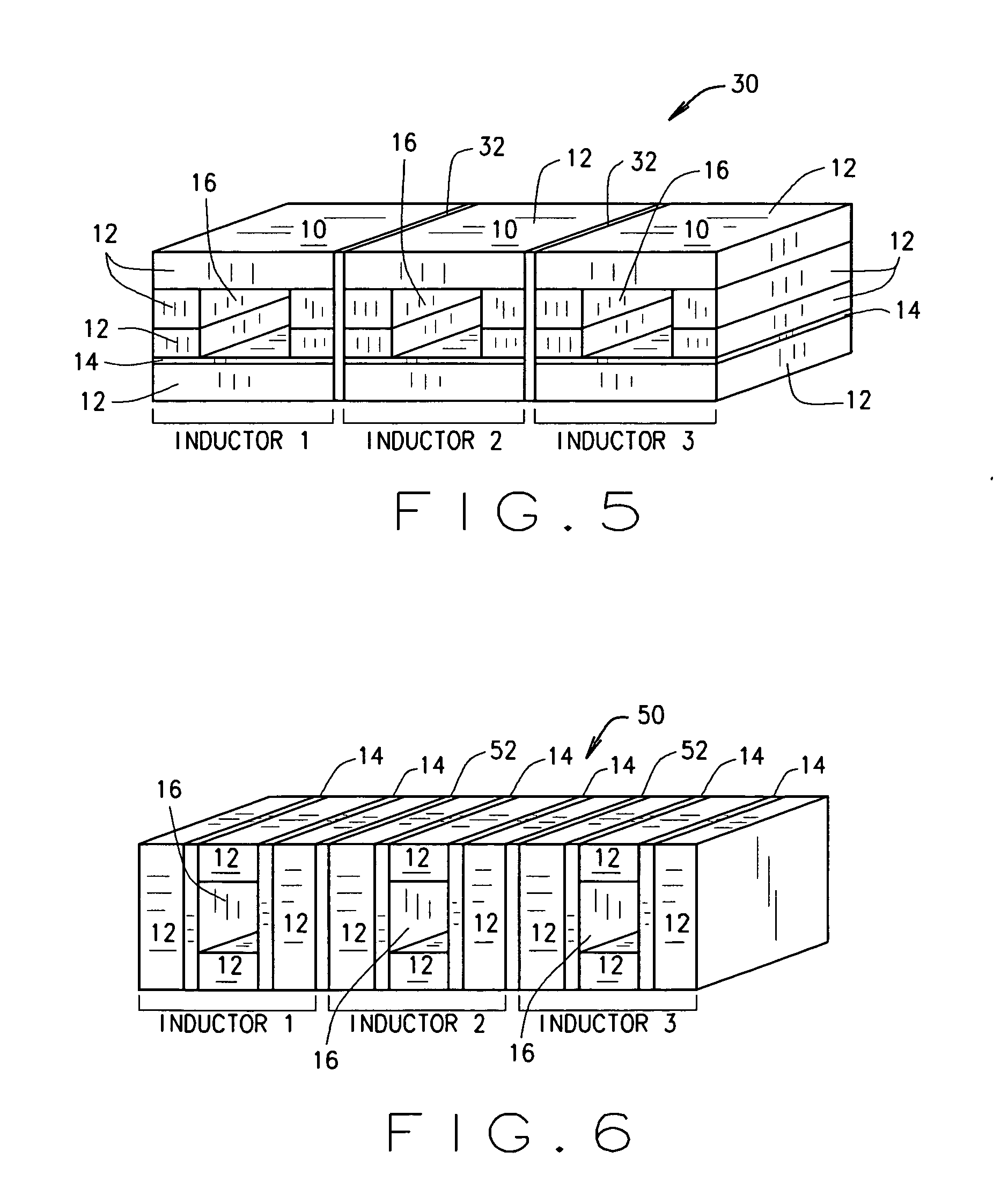
[0035]FIG. 5 is a gapped core structure 30 illustrating a multiple gapped core structure. Stacking layers 12, 14 of magnetic and non-magnetic materials as described above into a single structure can create multiple magnetic components, as described above, on a singular or unitary core structure 30. Thus, two, three or more magnetic components such as inductors, for example, can be built into one core structure 30, such as that illustrated in FIG. 5 when conductive elements, such as the conductor element 20 (shown in FIGS. 2 and 3) are placed through openings 16, or when conductive elements are otherwise formed on surfaces of the core structure 30.

[0036] Utilizing a unitary integrated core structure 30 for multiple magnetic components results in lower costs since packaging and handling of a single part is lower than the cost of handling many parts. Overall system costs can also be reduced, since placement of less parts should result in a cost savings. Yet another benefit is that the ...

third embodiment

[0041]FIG. 6 is an exemplary core structure 50 wherein a number of core structures are stacked one above the next and separated by a non-magnetic insulating layer 52. In the illustrated embodiment, each core structure includes two non-magnetic layers 14 sandwiched between magnetic layers 12, and insulating layers 52 extend between each cores structure and are substantially parallel to the layers 12, 14 of each core structure The nonmagnetic layers 14 define opposite sides of the conductor openings 16. The insulating layers 52 may be bonded between stacked layers 12, 14 either before or after openings 16 are formed, and core structure 50 is fired as a monolithic structure into its final form.

[0042] While stacked layers 12, 14 of core structure 50 includes three magnetic layers 12 and two non-magnetic layers 14, it is appreciated that greater or fewer numbers of-magnetic layers 14 may be employed with greater or fewer number of magnetic layers 12 without departing from the scope of th...


PUM

PropertyMeasurementUnit
magneticaaaaaaaaaa
conductiveaaaaaaaaaa
nonmagneticaaaaaaaaaa

Abstract

A magnetic component includes a first monolithic core structure having a plurality of magnetic layers and at least one nonmagnetic layer separating one of the plurality of magnetic layers from another of the plurality of magnetic layers. A first opening extends through the first core structure, and a conductive element establishes a conductive path through the first opening, wherein the nonmagnetic layer separates the conductive element from one of the magnetic layers.

Description

CROSS REFERENCE TO RELATED APPLICATIONS [0001] This application claims the benefit of U.S. Provisional Application Ser. No. 60 / 435,414 filed Dec. 19, 2002, the disclosure of which is hereby incorporated by reference in its entirety.BACKGROUND OF THE INVENTION [0002] This invention relates generally to manufacture of electronic components, and more specifically to manufacturing of magnetic components such as inductors. [0003] A variety of magnetic components, including but not limited to inductors and transformers, include at least one winding disposed about a magnetic core. In some components, a core assembly is fabricated from ferrite cores that are gapped and bonded together. In use, the gap between the cores is required to store energy in the core, and the gap affects magnetic characteristics, including but not limited to open circuit inductance and DC bias characteristics. Especially in miniature components, production of a uniform gap between the cores is important to the consi...

Claims


Application Information

Patent Timeline
Patent Type & Authority Applications(United States)
IPC IPC(8): H01F3/00H01F27/28H01F3/02H01F3/14H01F17/06H01F27/24
CPCH01F3/14H01F2017/065H01F17/06H01F3/02
Inventor ELLIOTT, BRENT ALANBOGERT, ROBERT JAMESHANLEY, RENFORD LAGUARDIA
Owner COOPER TECH CO
Why Eureka
Try Eureka