Lint trap

a technology of lint traps and traps, applied in the field of lint, can solve the problems of long-standing problems such as lint collection, potentially expensive repairs to be paid for by the home owner, and failure to teach a system suitable for adequately slowing down the discharge stream, etc., and achieve the effect of flow ra

Inactive Publication Date: 2005-01-06
SMOLLEY JOHN M
View PDF14 Cites 14 Cited by
  • Summary
  • Abstract
  • Description
  • Claims
  • Application Information

AI Technical Summary

Benefits of technology

[0013] As still yet another advantage, the present lint trap includes overflow ports that allow escape of water when the collection plate is full.
[0014] A further advantage is that the lint collection plate fills from the bottom up further allowing the flow rate of the water to slow before passing through the collection plate, e.g., allowing gravity to act as a separating force between the water and the lint.

Problems solved by technology

Lint collection has long been a problem with modern clothes washing machines.
The water and lint are then directed down a drain, perhaps in a utility sink, where the lint can clog the drain pipes causing potentially expensive repairs to be paid for by the home owner.
While these are configured to be joined to a utility sink, these references fail to teach a system suitable for adequately slowing the discharge stream sufficiently to allow good collection of lint.
Justice does disclose the sac can somehow be inverted and washed out for reuse, which is fraught with its own difficulties given its construction.
Typically, sacs tend to become loose prior to filling and “blow off” the hose from which the discharge water is expelled, potentially becoming a plug.

Method used


Image

  • Lint trap
  • Lint trap
  • Lint trap

Examples


Embodiment Construction

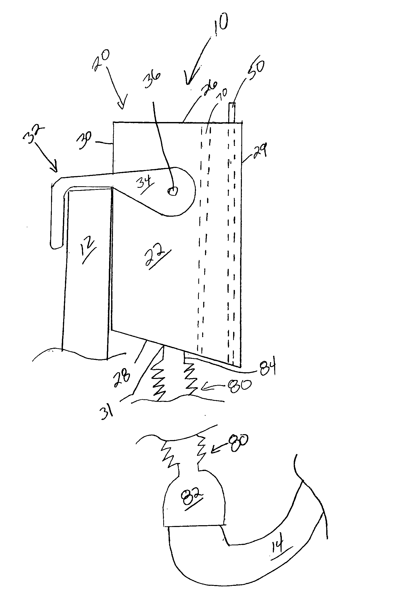
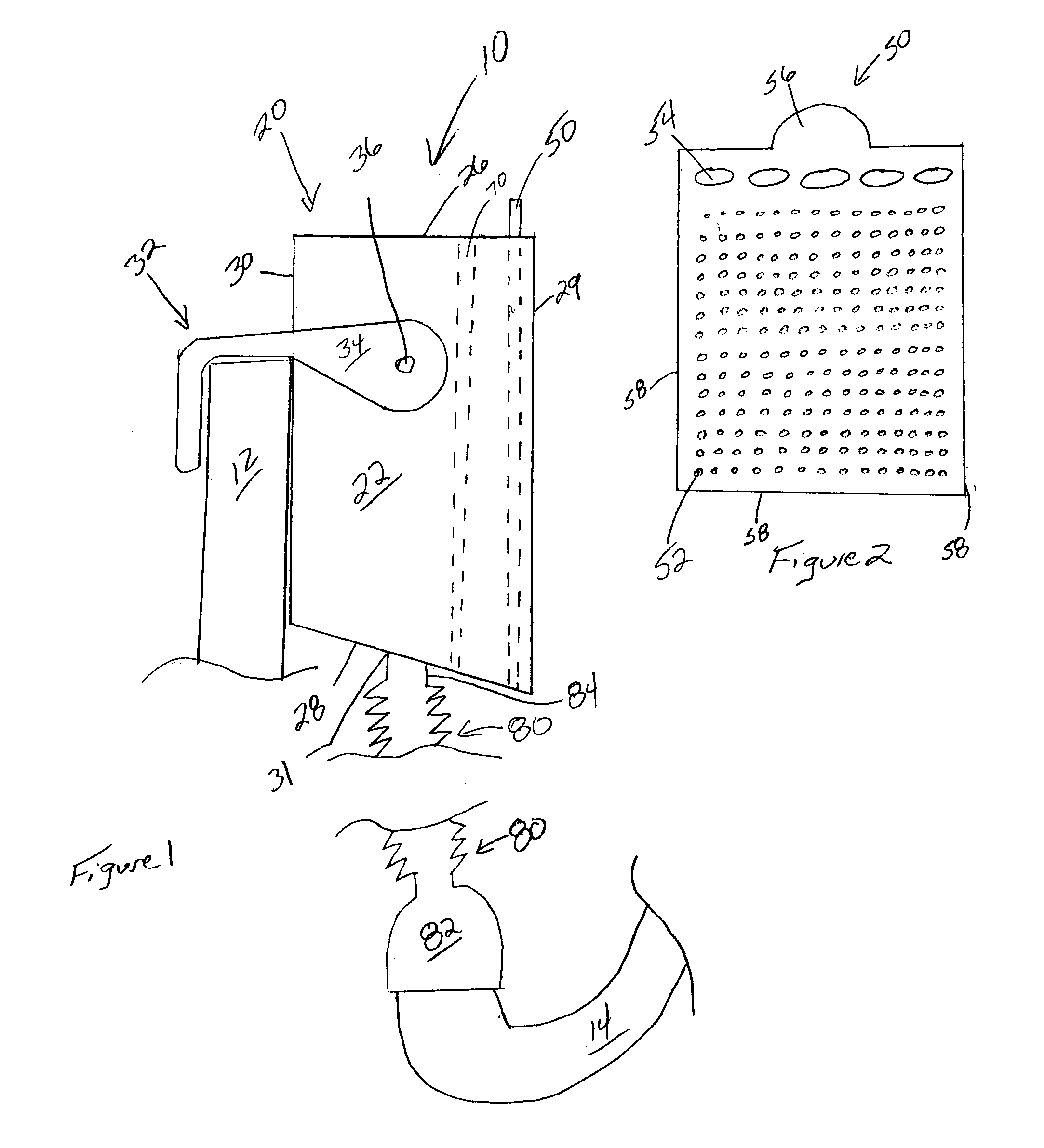
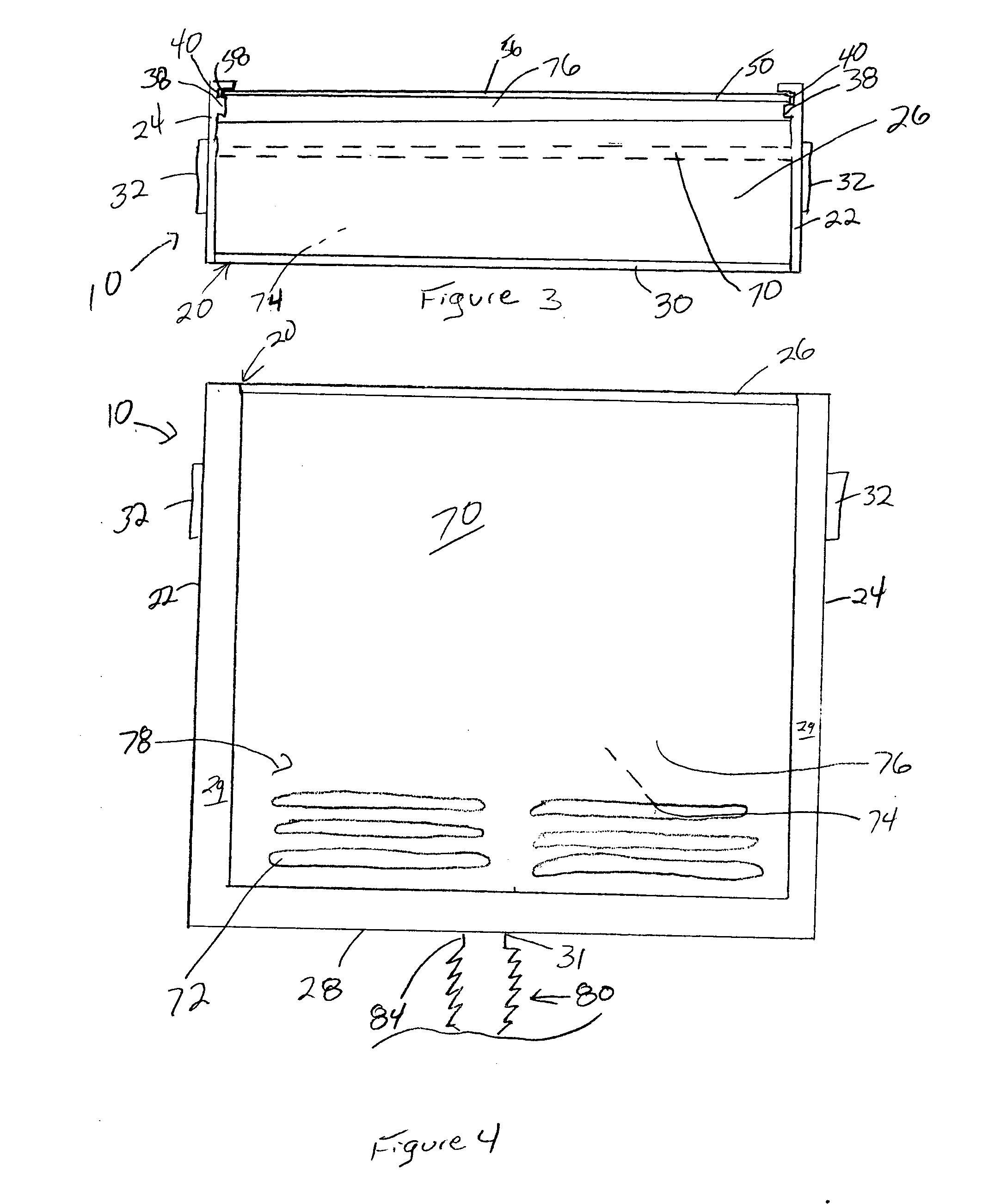
[0022] The lint trap 10 of the present invention is provided with a housing 20, a lint collection plate 50, a chamber divider wall 70 and an adapter 80. The chamber divider wall 70 may permanently separate the interior of the housing 20 into two chambers (described below). The lint collection plate 50 is removably received within the housing 20. The adapter 80 may communicate water from a washing machine hose 14 to the housing 20. Each of these components will be discussed in further detail below.

[0023] The housing 20 may have a first side wall 22, a second side wall 24, a top wall 26, a bottom wall 28, a front wall 29 and back wall 30. The bottom wall 28 may define an aperture 31. The bottom wall 28 preferably is positioned off horizontal, e.g., slanted, to cause water to move from adjacent the back wall 30 toward the front wall 29. The front wall 30 preferably is U-shaped as shown in the drawing, which is covered by the lint collection plate 50, when inserted.

[0024] At least one...


PUM

PropertyMeasurementUnit
perimeteraaaaaaaaaa
flow rateaaaaaaaaaa
pore sizeaaaaaaaaaa

Abstract

A lint trap, including a housing having a first side wall, a second side wall, a top wall, a bottom wall, a back wall and a front wall, and the bottom wall defining an aperture; at least one attachment mechanism joining the housing to a utility sink; a lint collection plate slot defined in the side walls; a lint collection plate, the lint collection plate being slidably received within the lint collection plate slot; and an adapter having a hose end and a trap end, the hose end being adapted to join to a hose of a washing machine and the trap end being joined relative to the aperture defined in the bottom wall and a method of use including the steps of flowing water into a flow rate control chamber of a lint trap; flowing water from the flow rate control chamber to a water release chamber; flowing water from the water release chamber through a lint collection plate; removing the lint collection plate from the lint trap; wiping lint off the lint collection plate; and reconnecting the lint collection plate to the lint trap.

Description

[0001] The present invention relates to lint traps for washing machines and more particularly reusable traps for collecting, removal and disposal of lint from streams of water and claims priority from provisional patent application No. 60 / 467,887, filed May 6, 2003 and entitled LINT TRAP.FIELD OF THE INVENTION BACKGROUND OF THE INVENTION [0002] Lint collection has long been a problem with modern clothes washing machines. Lint fibers knocked loose from the clothes float in the water in the washing machine until it is discharged out through a hose. The water and lint are then directed down a drain, perhaps in a utility sink, where the lint can clog the drain pipes causing potentially expensive repairs to be paid for by the home owner. A variety of solutions have been developed to capture the lint before it is directed down the sink drain. [0003] For example, U.S. Pat. No. 6,029,479 (Pattee), entitled Fine particle Lint Filter discloses a filtration device with a plurality of screens w...

Claims


Application Information

Patent Timeline
Patent Type & Authority Applications(United States)
IPC IPC(8): B01D35/00B01D35/027D06F39/10
CPCD06F39/10
Inventor SMOLLEY, JOHN M.
Owner SMOLLEY JOHN M
Why Eureka
Try Eureka