Flowmeter
a flowmeter and flow rate technology, applied in the direction of fluid speed measurement, liquid/fluent solid measurement, instruments, etc., can solve the problems of inability to perform correct measurement, inability to perform measurement, etc., to achieve reliable flow rate measurement, suppress the influence of flow variation, and high accuracy
- Summary
- Abstract
- Description
- Claims
- Application Information
AI Technical Summary
Benefits of technology
Problems solved by technology
Method used
Image
Examples
embodiment 1
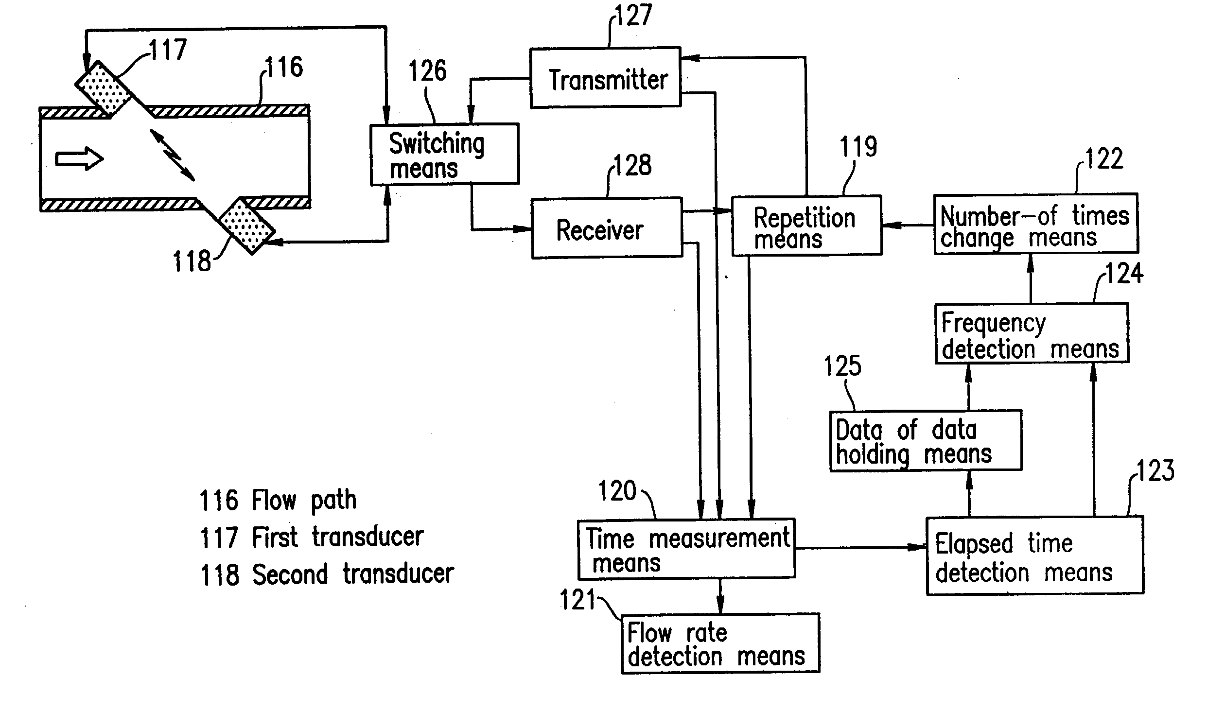
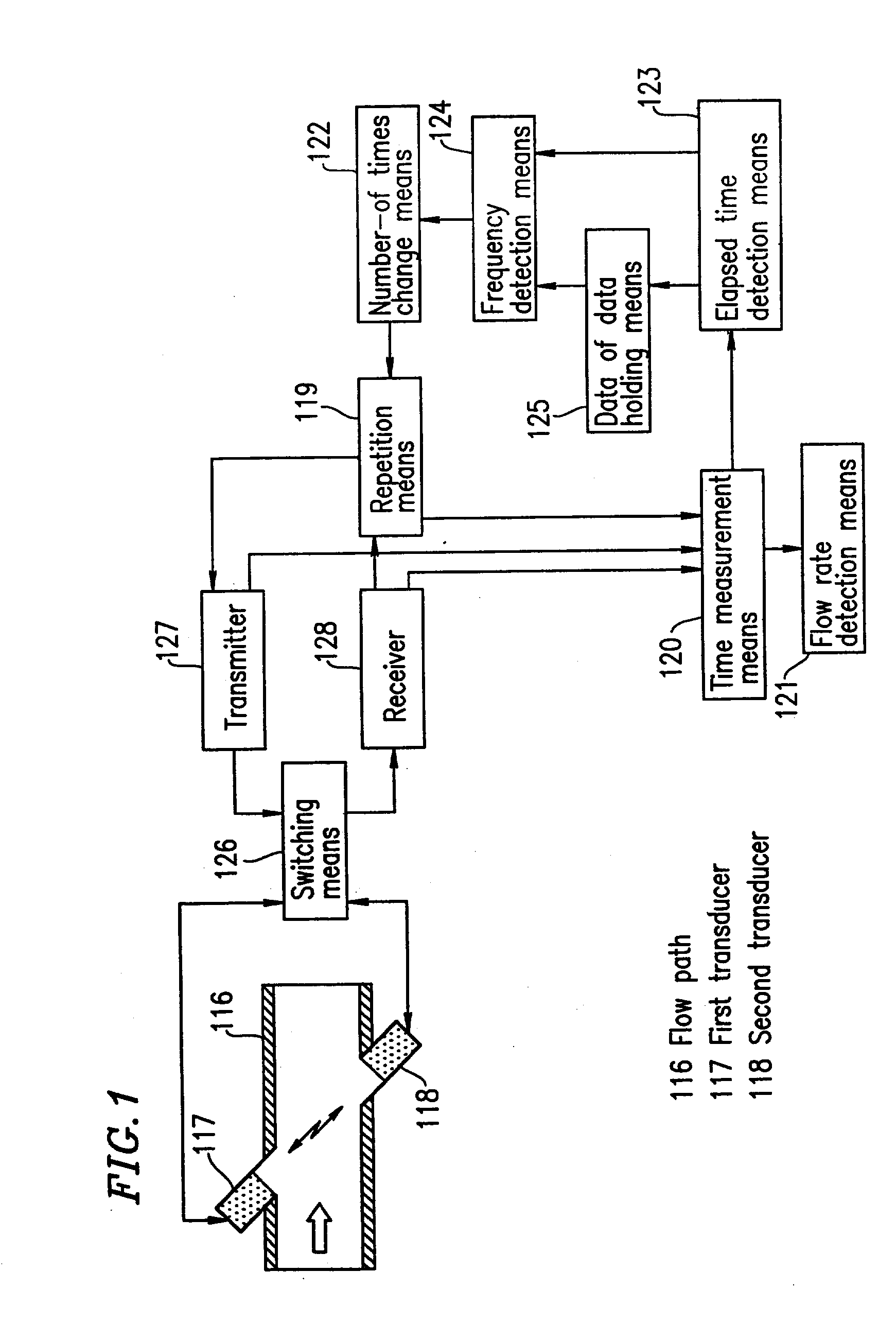
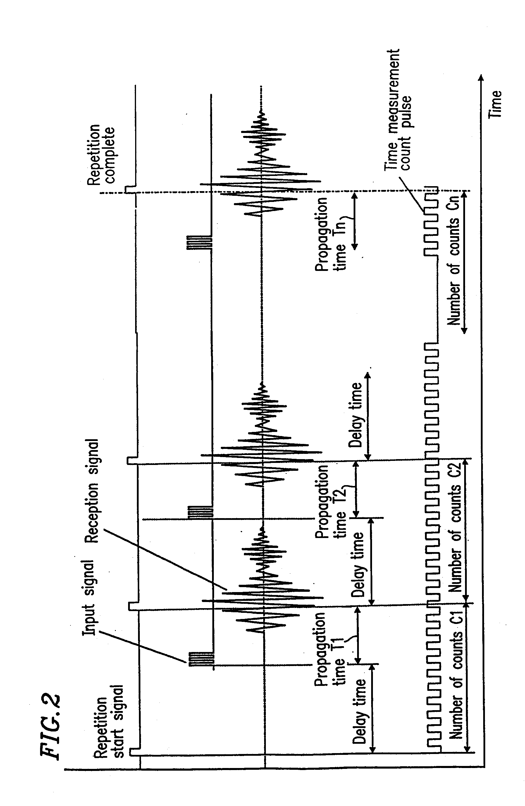
[0152] FIG. 1 is a block diagram showing a flowmeter of the present invention. In FIG. 1, reference numeral 117 is first transmission / reception means which is provided in a flow path 116 and which functions as transmission / reception means for transmitting / receiving a signal by using propagation of a sonic wave as a state change in a fluid. Reference numeral 118 is second transmission / reception means as transmission / reception means. Reference numeral 119 is repetition means for repeating signal propagation between the first transmission / reception means 117 and the second transmission / reception means 118. Reference numeral 120 is time measurement means for measuring a propagation time of a sonic wave propagated during the repetition in the repetition means 119. Reference numeral 121 is flow rate detection means for detecting the flow rate based on a value from the time measurement means 120. Reference numeral 122 is number-of-times change means for successively making a change to a p...
embodiment 2
[0157] FIG. 6 is a flowchart showing an operation of a flowmeter according to embodiment 2 of the present invention. Embodiment 2 is different from embodiment 1 in that the process of embodiment 2 is structured such that the number of repetition times which is determined according to a frequency obtained by the frequency detection means is used in the next flow rate measurement. The structure of the flowmeter in embodiment 2 is the same as that shown in FIG. 1.
[0158] As shown in FIG. 6, measurement of propagation time T1 of an ultrasonic wave propagating from the first transducer is performed, while time measurement information C.sub.i of the measurement means at that time is held in the data holding means. Measurement of propagation time T2 of an ultrasonic wave propagating from the second transducer is then performed, and the flow velocity and flow rate are calculated from times T1 and T2. Then, the frequency of a flow variation is detected from the held time measurement informati...
embodiment 3
[0160] FIG. 7 is a block diagram of a flowmeter according to embodiment 3 of the present invention. Embodiment 3 is different from embodiment 1 in that the flowmeter of embodiment 3 includes: flow rate variation identification means 129 to determine the magnitude of a flow rate variation detected by the flow rate detection means 121; and number-of-times change means 122 for changing the number of repetition times such that the flow rate variation identified by the flow rate variation identification means 129 is decreased, and that the flow rate variation identification means 129 operates using a standard deviation of the flow rate.
[0161] As shown in the flowchart of FIG. 8, the flow rate Qi is first measured. When the flow rate is equal to or higher than a predetermined value Qm (for example, 100 liter / hour), the number of repetition times is kept unchanged. When the flow rate is lower than a predetermined value Qm, standard deviation Hi is obtained based on n pieces of data before ...
PUM
 Abstract
Description
Claims
Application Information
 - R&D
- Intellectual Property
- Life Sciences
- Materials
- Tech Scout
- Unparalleled Data Quality
- Higher Quality Content
- 60% Fewer Hallucinations
Browse by: Latest US Patents, China's latest patents, Technical Efficacy Thesaurus, Application Domain, Technology Topic, Popular Technical Reports.
© 2025 PatSnap. All rights reserved.Legal|Privacy policy|Modern Slavery Act Transparency Statement|Sitemap|About US| Contact US: help@patsnap.com


