
Fusers and intermediate transfer members

Inactive Publication Date: 2004-12-16
HEWLETT PACKARD INDIGO BV
View PDF10 Cites 3 Cited by
  • Summary
  • Abstract
  • Description
  • Claims
  • Application Information

AI Technical Summary

Benefits of technology

[0012] The volatile liquid used to produce gas pressure in the drum in some embodiments need not be the liquid that is being pumped into and out of the drum to heat and cool the drum. The liquid transfer system which is used to pump the liquid into and out of the drum will work best if it uses a non-volatile liquid, free of gas. The volatile liquid used to produce gas pressure could be in a thin outer region just beneath the outer surface of the drum. The liquid being pumped into and out of the drum could fill a separate, more central portion of the drum, below the outer region, sealed off from the outer space but in good thermal contact with it.
[0013] In some embodiments, the hot liquid reservoir has a heating element and thermostat, and / or the cold liquid reservoir has a refrigeration element and a thermostat, to maintain the hot liquid and the cold liquid at the desired temperature. The hot liquid reservoir, unlike a drum with a thin membrane, can be kept well insulated thermally, and it can be kept some distance away from the parts of the printer or copier that require frequent handing (for example, to remove paper jams), so there will be little danger that someone will be burned by touching it. The hot liquid reservoir can also be designed to withstand much higher gas pressure than a drum using a thin membrane, since it can have thick walls, so there will be little danger of it exploding. It can also be kept at a higher temperature than the desired final temperature of the liquid, so that the final temperature, after the change of liquid in the drum, will be the desired final temperature. For both these reasons, it will be safe to keep the liquid in the hot liquid reservoir heated all the time. Having good thermal insulation around the hot liquid reservoir and the cold liquid reservoir also means that it will not require much power to maintain the hot liquid and the cold liquid at their desired temperatures.
[0028] In an embodiment of the invention, there is an accumulator in the hot liquid reservoir which allows the volume of liquid in the hot liquid reservoir to change substantially without a commensurate change in liquid pressure.
[0029] In an embodiment of the invention, there is an accumulator in the cold liquid reservoir which allows the volume of liquid in the cold liquid reservoir to change substantially without a commensurate change in liquid pressure.
[0032] In an embodiment of the invention, there is an accumulator in the liquid-containing region which allows the volume of liquid in the liquid-containing region to change substantially without a commensurate change in liquid pressure.

Problems solved by technology

But maintaining air under pressure inside the drum would require a pumping system, and a spongy layer can easily become damaged, and thermally insulates the surface from the source of heat inside the drum.
There are some disadvantages to using a drum with liquid in it, particularly a drum whose outer surface is a thin membrane supported by gas pressure.
The liquid can have a high heat capacity, and hence take a long time to heat up.
This means there may be a long waiting time when the copier or printer is first turned on, until it is ready to print.
To avoid waiting, the drum may be kept hot all the time, but this can be dangerous, because someone inadvertently touching the drum could be burned, and because the drum could explode if the gas pressure inside gets too high.
If the surface of the drum is a thin somewhat flexible membrane, then it cannot be built to withstand very high pressure.
Using liquid with high heat capacity also means that, if the gas pressure does get too high, it will take a long time to bring the pressure down by cooling off the liquid.
The heating problem is especially acute if a large amount of liquid is used.

Method used


Image

  • Fusers and intermediate transfer members
  • Fusers and intermediate transfer members

Examples


Embodiment Construction

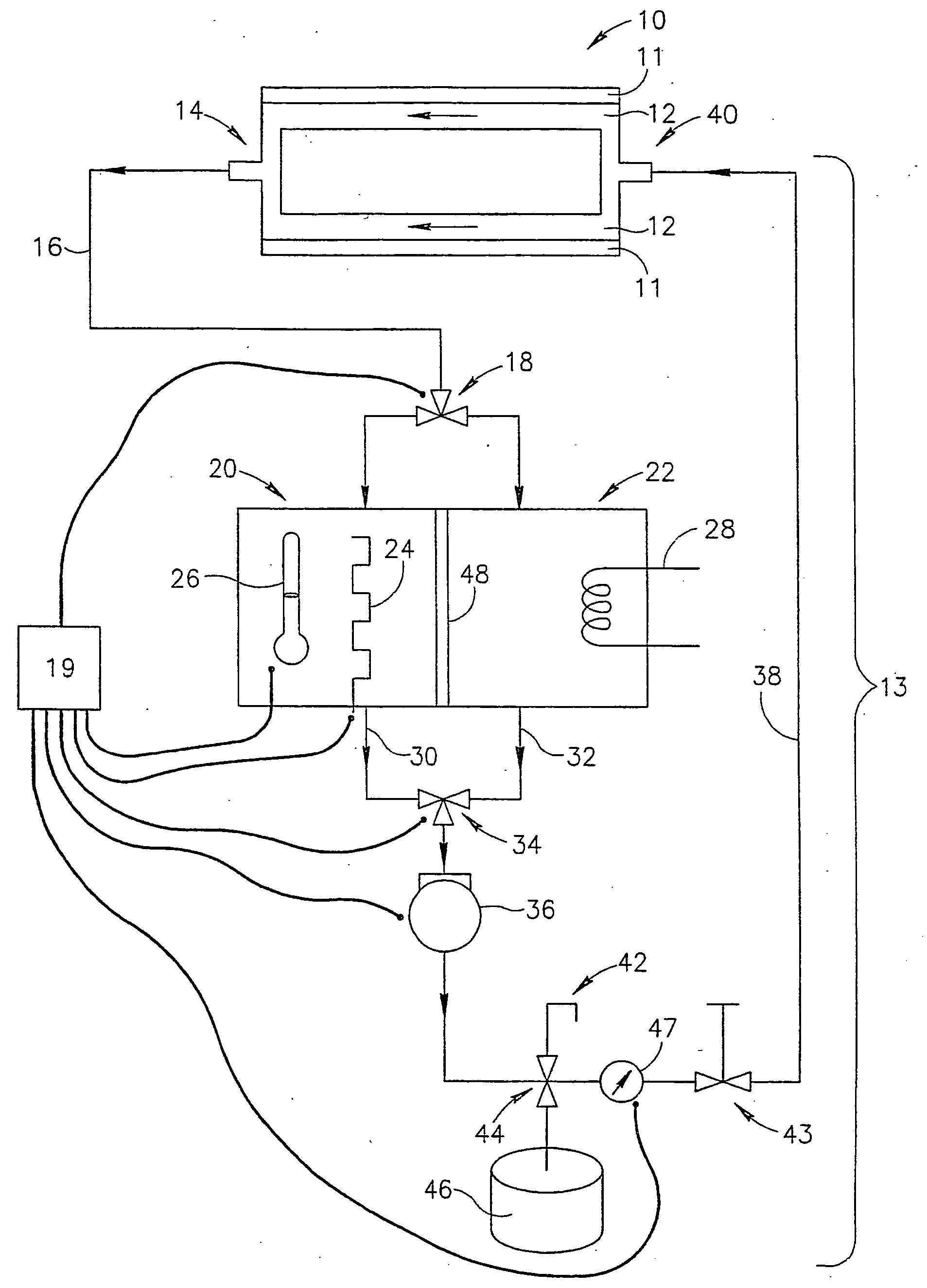
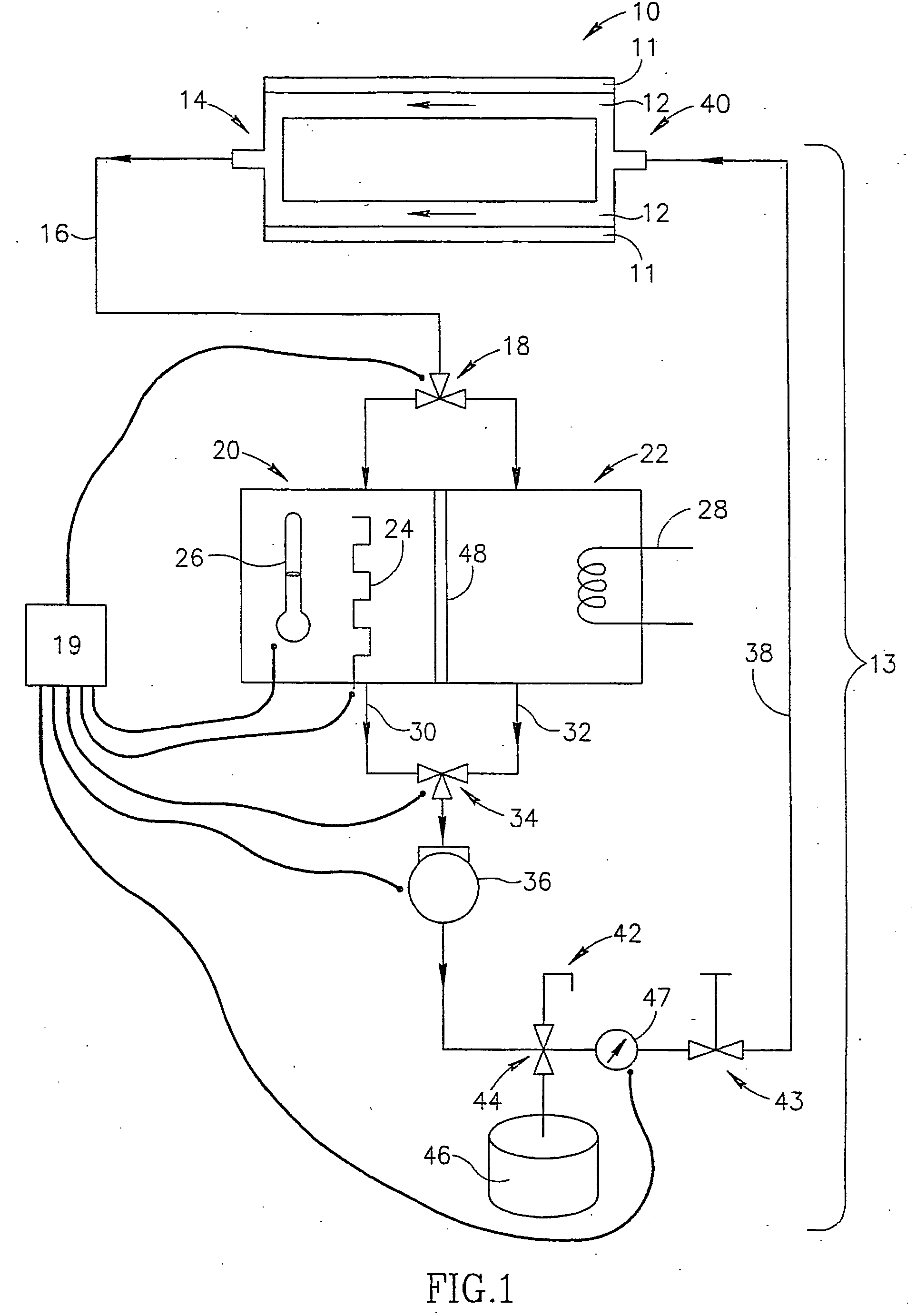
[0053] The embodiment shown in FIG. 1 has a drum 10, with a region 12 filled with a liquid. Optionally, there is a thin outer region 11, between region 12 and the outer surface of drum 10, which contains its own liquid, optionally a different liquid more volatile than the liquid in region 12, which maintains gas pressure supporting the outer surface when the drum is hot. Generally, the liquid in region 12 need not be replaced when the temperature of the drum is to be changed. Region 12 is connected to a liquid transfer system 13, consisting of pipes, connectors, valves, and reservoirs. An outlet 14 of region 12 connects region 12 to a return pipe 16. In those embodiments where there is an outer region 11 between region 12 and the outer surface of drum 10, region 12 optionally remains fixed in place while drum 10 is rotating. In this case, outlet 14 is optionally an ordinary pipe connector. If region 12 rotates with the outer surface of drum 10, then outlet 14 optionally comprises a ...


PUM


Abstract

Drum intermediate transfer member or fuser apparatus, for use in a printer or copier, comprising: a drum having a drum surface and including a liquid-containing region in the interior of the drum thermally connected to the drum surface, such that the liquid is capable of heating and cooling the drum surface; and a liquid transfer system including a hot liquid reservoir, a cold liquid reservoir, at least one pump, pipes and optionally at least one valve arranged to selectively pump liquid between the liquid-containing region and the hot liquid reservoir, and between the liquid-containing region and the cold liquid reservoir.

Description

[0001] The present invention is related to the field of printers and copiers and more particularly to fusers, intermediate transfer members, and / or elements that function as both fusers and intermediate transfer members and to printers or copiers that utilize the same.[0002] Printers and copiers are well known. Modern copiers that utilize powder or liquid toners comprising toner particles to form visible images generally form a latent electrostatic image on an image forming surface (such as a photoreceptor), develop the image utilizing a toner (such as the aforementioned powder or liquid toners) to form a developed image and transfer the developed image to a final substrate. The transfer may be direct, i.e., the image is transferred directly to the final substrate from the image forming surface, or indirect, i.e., the image is transferred to the final substrate via one or more intermediate transfer members.[0003] In general, the image on the final substrate must be fused and fixed t...

Claims


Application Information

Patent Timeline
IPC IPC(8): G03G15/16G03G15/20
CPCG03G15/1605G03G15/2053G03G15/161
Inventor ROMEM, ILAN
Owner HEWLETT PACKARD INDIGO BV
Learn More