
Fuel dispenser filter with removable filter media

a filter media and fuel dispenser technology, applied in the direction of cartridge filters, filtration separation, separation processes, etc., can solve the problems of hazardous waste generated by spin-on type filters, spillage, and spillage during the change of spin-on type filters, and achieve the effect of reducing hazardous was

Inactive Publication Date: 2004-11-04
CHAMPION LAB
View PDF12 Cites 18 Cited by
  • Summary
  • Abstract
  • Description
  • Claims
  • Application Information

AI Technical Summary

Benefits of technology

[0007] An object of the present invention is to provide an improved fuel dispenser filter that can be used for diesel, gasoline, and gasoline-alcohol combination fuels and greatly reduces the hazardous wastes generated by filter changes.
[0008] Another object of the present invention is to provide an improved fuel dispenser filter to reduce the spillage of fuel during the filter changing process.
[0009] A further object of the present invention is to provide an improved fuel dispenser filter with an easily and safely replaceable filter element that removes solid particulate in the fuel.

Problems solved by technology

Presently, some spillage will occur during the changing of spin-on type filters.
Spillage will also occur while removing a spin-on filter from the dispenser due to having to tip the full filter to clear dispenser components.
The hazardous waste generated by spin-on type filters is a problem.
Compressing the spin-on filter unit will reduce volume by approximately two-thirds, but this is still substantial.
This size can still be costly to dispose of.

Method used


Image

  • Fuel dispenser filter with removable filter media
  • Fuel dispenser filter with removable filter media
  • Fuel dispenser filter with removable filter media

Examples


Embodiment Construction

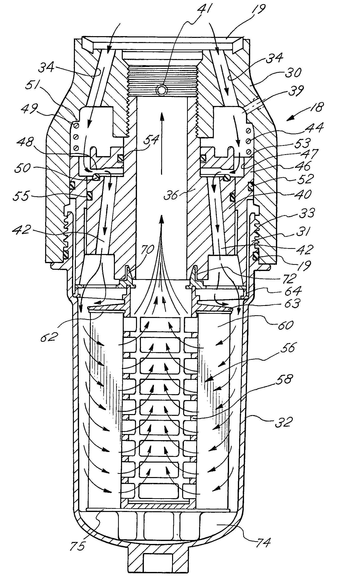
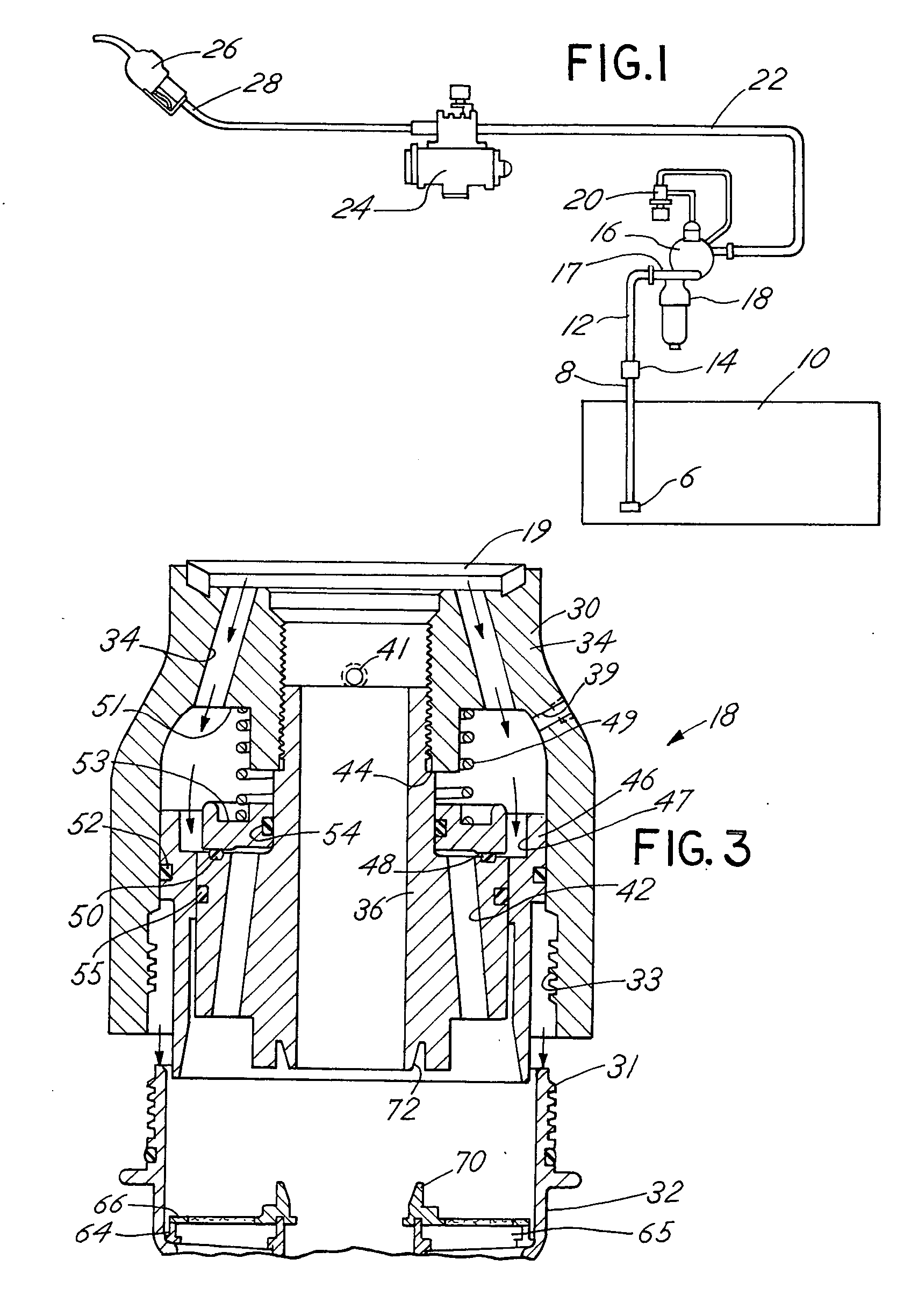
[0027] There is shown in FIG. 1 a typical service station fuel dispenser installation that can incorporate the fuel dispenser filter of the present invention. The installation, which can be a gas station, for example, incorporates a reservoir or storage tank 10 either above the ground or below the ground, which contains the fuel to be dispensed. The fuel can be diesel, gasoline, or a gasoline-alcohol blend. A submersible pump 6 is located on the end of line 8 and submerged in storage tank 10 near the bottom. Line 8 is then connected to shear valve 14. A line 12 is connected from the shear valve 14 and extends upwardly for connection to the fuel dispenser filter 18 of the present invention. The fuel dispenser filter 18 is connected to the manifold 17 of the primary valve 16, which is activated by a two-stage pilot valve 20. Extending from the primary valve 16 is line 22 that communicates with a fuel meter 24 that is connected to a nozzle 26 by a line 28.

[0028] In operation, fuel pass...


PUM

PropertyMeasurementUnit
mean pore sizeaaaaaaaaaa
phase separationaaaaaaaaaa

Abstract

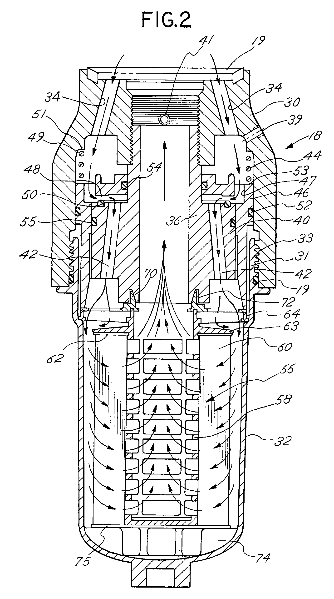
A fuel dispenser filter for filtering fuel is adapted to be connected to a support in a fuel distribution system. The filter comprises a housing including an adaptor constructed and arranged to be secured to the support and a bowl operatively connected to the adaptor. A stud / spacer is secured in the adaptor. The stud / spacer defines a centrally disposed outlet flow passage and outwardly disposed inlet flow passages. A sleeve member is movably supported in the adaptor between the stud / spacer and the adaptor. The sleeve member is constructed and arranged to open and close the fuel flow through the inlet flow passages. A filter assembly including filter media is provided in the bowl for filtering the fuel passing through the filter. When the bowl is firmly engaged with the adaptor, the sleeve member is moved to open position to permit the flow of fuel through the filter and when the bowl is removed from the adaptor, the sleeve member is moved to a closed position to stop the flow of fuel. A spring is provided to bias the sleeve member to the closed position when the bowl is removed from the adaptor. Various seals are provided within the filter to confine fuel flow to the desired flow paths.

Description

[0001] A. Field of the Invention[0002] This invention pertains to a removable element--type filter to replace the current spin-on type filter used in a dispenser for fuel in gas stations. The removable element-type filter may be retrofit to existing installations to replace current spin-on filters to remove particulate matter in specific fuels. It has provisions to sense water in gasoline and phase separation in an alcohol-gasoline combination. More particularly, the present invention will reduce spillage of fuel during filter changes at a gas station and will reduce the volume of hazardous waste generated with a spin-on type filter.[0003] B. Description of Related Art[0004] It is common in the United States and around the world to use a spin-on filter to filter diesel fuel, gasoline and an alcohol-gasoline combination for particulate matter and sense water in these fuels.[0005] Presently, some spillage will occur during the changing of spin-on type filters. Spin-on filters will ove...

Claims


Application Information

Patent Timeline
Patent Type & Authority Applications(United States)
IPC IPC(8): B01D35/153
CPCB01D35/153B01D2201/0415B01D2201/34B01D35/306
Inventor GRUCA, MICHAEL J.HAHN, DAVID E.ATTEBERRY, W. SCOTT
Owner CHAMPION LAB
Learn More