
Wavelength-multiplexed narrow-bandwidth optical transmitter and wavelength-multiplexed vestigial-side-band optical transmitter

a wavelength-multiplexed, optical transmitter technology, applied in multiplex communication, optical elements, instruments, etc., can solve the problems of increasing the cost of wavelength band and frequency width, the upper limit of its characteristics is limited, and the cost of increasing the cos

Inactive Publication Date: 2004-10-21
HITACHI LTD
View PDF2 Cites 52 Cited by
  • Summary
  • Abstract
  • Description
  • Claims
  • Application Information

AI Technical Summary

Benefits of technology

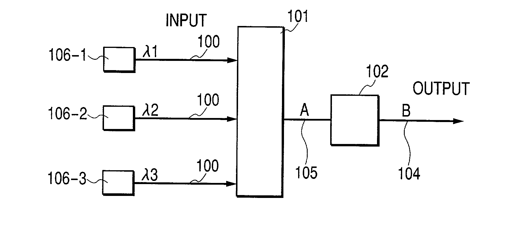
[0148] According to the present invention, it is possible to provide a higher performance optical VSB method and a higher performance optical bandwidth narrowing method. From the viewpoint of a configuration, the present invention can reduce the number of narrow band-pass optical filters, which are required when the optical VSB method or the optical bandwidth narrowing method is used, to a large extent.[0149] In addition, according to another aspect of the present invention, using a wavelength interleave configuration enables improvement in characteristics of a periodic narrow band-pass optical filter, and also enables reduction in crosstalk, which is caused by light signals having adjacent wavelengths, at the same time.[0150] In addition, by means of the wavelength stabilization technique according to the present invention, positional relation between a center wavelength of a light signal and a center wavelength of an optical filter can be stabilized with a high degree of accuracy, with the result that degradation in transmission characteristics and a waveform, and occurrence of crosstalk, can be prevented.[0151] In addition, according to another aspect of the present invention, a VSB light signal and a narrow-bandwidth light signal can be obtained using a constant wavelength interval and an absolute wavelength decided by the ITU standards. Therefore, if a wavelength of a light source is made tunable, its range can be extended.[0152] Reference numerals are as follows: 100 Input optical fiber, 101 First optical wavelength multiplexer, 102 Periodic narrow band-pass optical filter, 103 Second optical wavelength multiplexer, 104 Output optical fiber, 105 Optical fiber, 106 Signal light source, 107 Optical coupler, 108 Optical waveguide, 109 Interleaver with narrow band-pass optical filter, 110 Semiconductor light source, 111 Temperature control circuit, 112 Optical demultiplexer, 113 Narrow band-pass optical filter, 114 Photodetector, 115 Subtraction circuit, 116 Zero-point control circuit, 117 Control signal, 118 Narrow band-pass optical filter with wavelength deviation detecting function, 120 Wavelength optical filter, 122 Sinusoidal oscillator, 123 Adder, 124 Band-pass filter, 125 Error signal, 130 Beam collimator, 131 Beam splitter, 132 Fabry-Perot etalon, 133 Photodiode, 134 Temperature stabilization substrate, 135 Beam sampler, 136 Optical VSB signal, 137 Wavelength reference device, 138 Wavelength error detecting unit, 139 Optical power detection signal, 140 Temperature control unit, 141 Temperature control signal

Problems solved by technology

However, an upper limit of its characteristics is limited by an amplification wavelength band of an optical amplifier such as an optical fiber amplifier to which a rare-earth element is added, such as EDFA (Erbium-doped Fiber Amplifier); a semiconductor optical amplifier; or an optical fiber Raman amplifier.
If an L-band optical amplifier or a Raman amplifier is used, the range of the wavelength band and the frequency width can be increased by several times. However, decrease in pumping efficiency causes increase in costs and decrease in performance of the optical amplifier.
Although both of the techniques are broadly used in radio communication, and the like, there is no example, which has become commercially practical, at present in the field of optical fiber communication.
Using this example, disadvantages of the conventional methods relating to both of the techniques will be described.
This results in increase in costs, and a configuration of a transmitter becomes complicated.
In addition, there is another disadvantage that because center wavelengths of these optical filters are different from one another, and also because it is necessary to control bandwidths of the optical filters with a high degree of accuracy (about one-tenth of a signal bit rate), resulting in difficulty in production, and in increase in kinds of spare parts and labor of management.
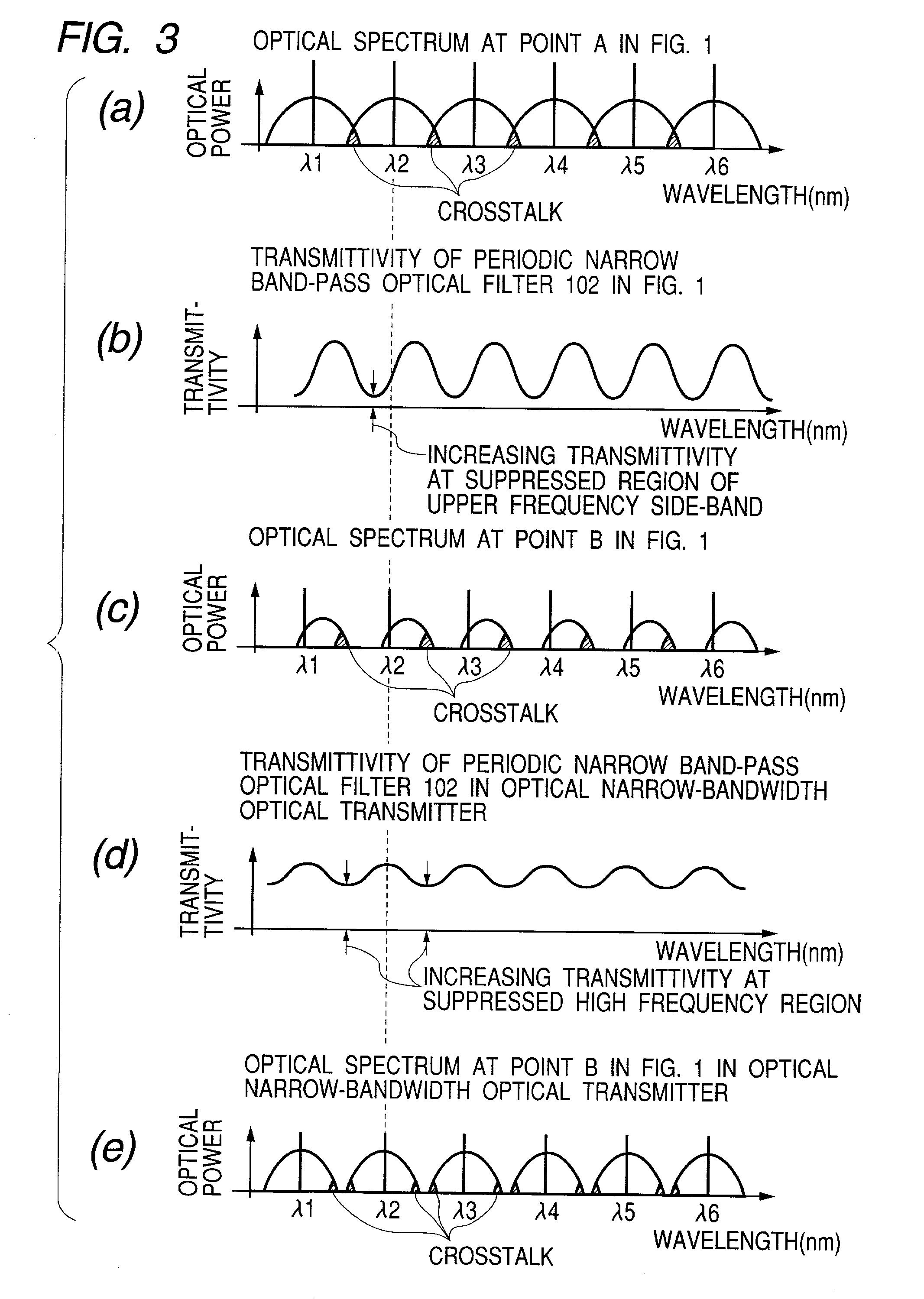
Therefore, an error, which occurs between both, produces a great deterioration in characteristics such as transmission distance and crosstalk to adjacent wavelengths.
As a result, a control error is easily produced.
However, concerning how to control wavelength relation among the wavelength reference device, a signal wavelength, a narrow band-pass optical filter, which relate to a conventional wavelength-multiplexed narrow-bandwidth optical transmitter and a conventional VSB optical transmitter, no specific solution has been presented in the past.
Wavelength deviation, which occurs in the wavelength relation, causes deteriorations in a waveform and transmission characteristics of a light signal, and also causes crosstalk between wavelength-multiplexed signals.
This produces the following disadvantages: a range within which a wavelength can be tuned is limited; wavelength tunable speed decreases; and the like.
In addition, in the case of the wavelength-multiplexed narrow-bandwidth optical transmitter, there are also substantially the same problems.
To be more specific, the number of required optical filters is the same as the number of light signals to be wavelength-multiplexed, which produces the following problems: increase in costs; complication of structure; difficulty in production and management of an optical filter; and the like.
Furthermore, it is difficult to change a wavelength of a transmission light source to a large extent.

Method used


Image

  • Wavelength-multiplexed narrow-bandwidth optical transmitter and wavelength-multiplexed vestigial-side-band optical transmitter
  • Wavelength-multiplexed narrow-bandwidth optical transmitter and wavelength-multiplexed vestigial-side-band optical transmitter
  • Wavelength-multiplexed narrow-bandwidth optical transmitter and wavelength-multiplexed vestigial-side-band optical transmitter

Examples


first embodiment

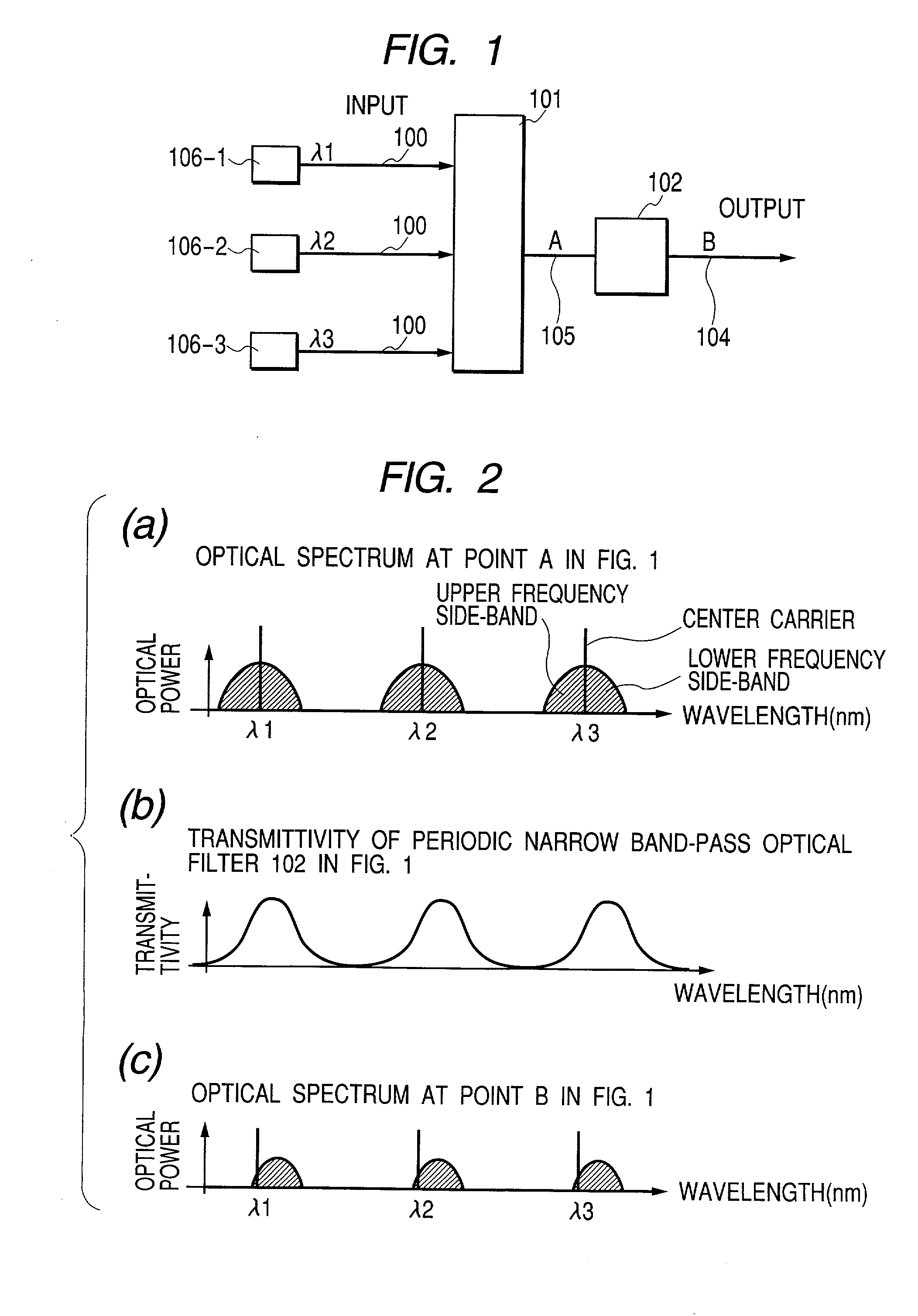
[0048] FIG. 1 is a configuration diagram illustrating the present invention. It shows a configuration of a wavelength-multiplexed vestigial-side-band (VSB) optical transmitter according to the present invention. Its essential parts will be described as follows. To be more specific, output light of three signal light sources 106-1, 106-2, 106-3 having different wavelengths one another (wavelengths .lambda.1, .lambda.2, .lambda.3) is led to a first optical wavelength multiplexer 101 through input optical fibers 100, and is then wavelength-multiplexed. After that, a periodic narrow band-pass optical filter 102, which has periodic transmittivity relating to an input wavelength, filters the wavelength-multiplexed light collectively, and converts the filtered light into an optical VSB signal, which is output from an output fiber 104.

[0049] FIG. 2 illustrates principles of the present invention using optical spectra. FIG. 2(a) illustrates a spectrum of a light signal at an output point (po...

second embodiment

[0059] FIG. 4 is a configuration diagram illustrating the present invention. This example solves disadvantages found in the first embodiment of the present invention described above. This embodiment has a configuration in which crosstalk at the time of improvement in wavelength density is reduced by further wavelength-multiplexing the wavelength-multiplexed signal in FIG. 1 with another wavelength-multiplexed signal using a wavelength multiplexer such as an interleaver or and an optical coupler. Signal light sources 106-1, 106-3, 106-5 (wavelengths .lambda.1, .lambda.3, .lambda.5), which are odd number wavelengths if they are counted from the short wavelength side, are led to a first optical multiplexer 101-1 through input optical fibers 100, and are wavelength-multiplexed. In addition, signal light sources 106-2, 106-4, 106-6, which have even number wavelengths (wavelengths .lambda.2, .lambda.4, .lambda.6), are also wavelength-multiplexed in the second optical wavelength multiplexe...

third embodiment

[0068] FIG. 10 illustrates the present invention. To be more specific, FIG. 10 illustrates a configuration in which light signals are wavelength-multiplexed while the light signals are interleaved every three wavelengths in increasing order of wavelength. In other words, light signals are divided into three sets, that is to say, wavelengths 3N+1, 3N+2, and 3N (N is an integer); each of the sets is wavelength-multiplexed by the first optical wavelength multiplexers 101-1, 101-2, 101-3 according to the present invention respectively to convert it into a wavelength-multiplexed signal; and each of the wavelength-multiplexed signals is converted into a VSB signal by periodic narrow band-pass optical filters 102-1, 102-2, 102-3 respectively. Each spectrum of the light signals is shown in FIGS. 11(a), 11(b), 11(c) respectively. It is to be noted that the figures show only a part (six wavelengths) of optical spectra. After that, these light signals are wavelength-multiplexed by the second o...


PUM


Abstract

Objects of the present invention are to reduce the number of optical filters, and to improve crosstalk characteristics of periodic optical filters. WDM signals are converted into vestigial-side-band signals collectively using a periodic optical filter. As an example, light signals having odd number wavelengths (wavelengths lambda1, lambda3, lambda5) and light signals having even number wavelengths (wavelengths lambda2, lambda4, lambda6) are wavelength-multiplexed in the first optical wavelength multiplexer, and are then filtered by a periodic narrow band-pass optical filter to convert the light signals into vestigial-side-band (VSB) signals. Then, the vestigial-side-band signals are combined by the second optical wavelength multiplexer. Such an interleave configuration enables suppression of crosstalk caused by adjacent channels.

Description

[0001] 1. Field of the Invention[0002] The present invention relates to an optical wavelength-multiplexed bandwidth narrowing method and an optical vestigial-side-band transmission method (VSB), which are used for reducing bandwidths of light signals in optical information communication using optical fibers, and to configurations of optical transmitters using these methods.[0003] 2. Related Art[0004] Wavelength division multiplexing (WDM) optical transmission method is a very effective technique for increasing the capacity of optical fiber communication; in this method, a plurality of optical signals, each of which has a wavelength different from the other, are multiplexed in an optical fiber to transmit information. In recent years, a wavelength division multiplexing optical transmission device, the number of wavelengths of which is more than 100, and total transmission capacity of which is more than 1 Tbit / s, is being commercialized. Experimentally, realization of a transmission s...

Claims


Application Information

Patent Timeline
IPC IPC(8): H04J14/00G02B6/34H04B10/07H04B10/2507H04B10/548H04B10/572H04J14/02
CPCG02B6/29358G02B6/2938G02B6/4246H04B10/503H04B10/5165
Inventor KIKUCHI, NOBUHIKOHAYASE, SHIGENORITAKEYARI, RYOJI
Owner HITACHI LTD
Learn More