
Adaptive antenna array and method of controlling operation thereof

Inactive Publication Date: 2004-10-14
GOOGLE TECH HLDG LLC
View PDF5 Cites 37 Cited by
  • Summary
  • Abstract
  • Description
  • Claims
  • Application Information

AI Technical Summary

Benefits of technology

[0022] The present invention provides better translation of the uplink estimate to the downlink estimate by assuming a worst case scenario when the downlink communication is initiated. An advantage of the invention is that, depending upon the changing propagation conditions due, for example, to the movement of a mobile station, the downlink may be continually monitored and, consequently, optimisation of the downlink communication (in terms of beam width and power control) may be managed dynamically (based, for example, on QoS) during a call.

Problems solved by technology

An attainable degree of prediction accuracy of a downlink estimate limits the capacity and frequency re-use that is achievable by any adaptive antenna network since an explicit downlink channel estimate is not available to the base station at which the antenna network is located.
One problem with this procedure is that it can lead to a dramatic alteration of the estimated direction in successive principle downlink estimates.
More specifically, attempts to track a moving mobile unit by using such instantaneous snapshots can be ineffective and / or complex (i.e. processing intensive) because the uplink to downlink error is a function of the speed and propagation conditions of the mobile unit.
Although adaptive antennas, in general, reduce co-channel interference in an antenna network when the uplink and downlink directional estimates are the same as the downlink direction, any error between the actual downlink direction and the downlink estimate causes a significant reduction in the C / (I+N) and an increase in overall system interference.
The increased power used in the narrow beam therefore has increased reach and so the carrier frequency used in the downlink causes adjacent splutter (i.e. co-channel and / or adjacent channel interference) in an adjacent cell.
Moreover, this increased power downlink transmission is likely to still be directionally incorrect since directional convergence between the uplink and downlink estimates may not yet have taken place.
Therefore, at some point, downlink power concentrated in an originally narrow beam becomes a significant problem because, with ever-increasing radial displacement, the area covered by the narrow beam increases.
System interference therefore increases because the power within the narrow beam acts to offset the affects of signal attenuation.
In other words, with the downlink direction wrongly estimated, operation of the system to maximise / improve QoS results in more power being steered in an incorrect direction, thereby increasing system interference (as a whole) until downlink and uplink directional estimation convergence occurs.
Increasing the aperture of the beam reduces the chances of encountering directional estimation errors but increases the interference seen by the co-channel mobile.

Method used


Image

  • Adaptive antenna array and method of controlling operation thereof
  • Adaptive antenna array and method of controlling operation thereof
  • Adaptive antenna array and method of controlling operation thereof

Examples


Embodiment Construction

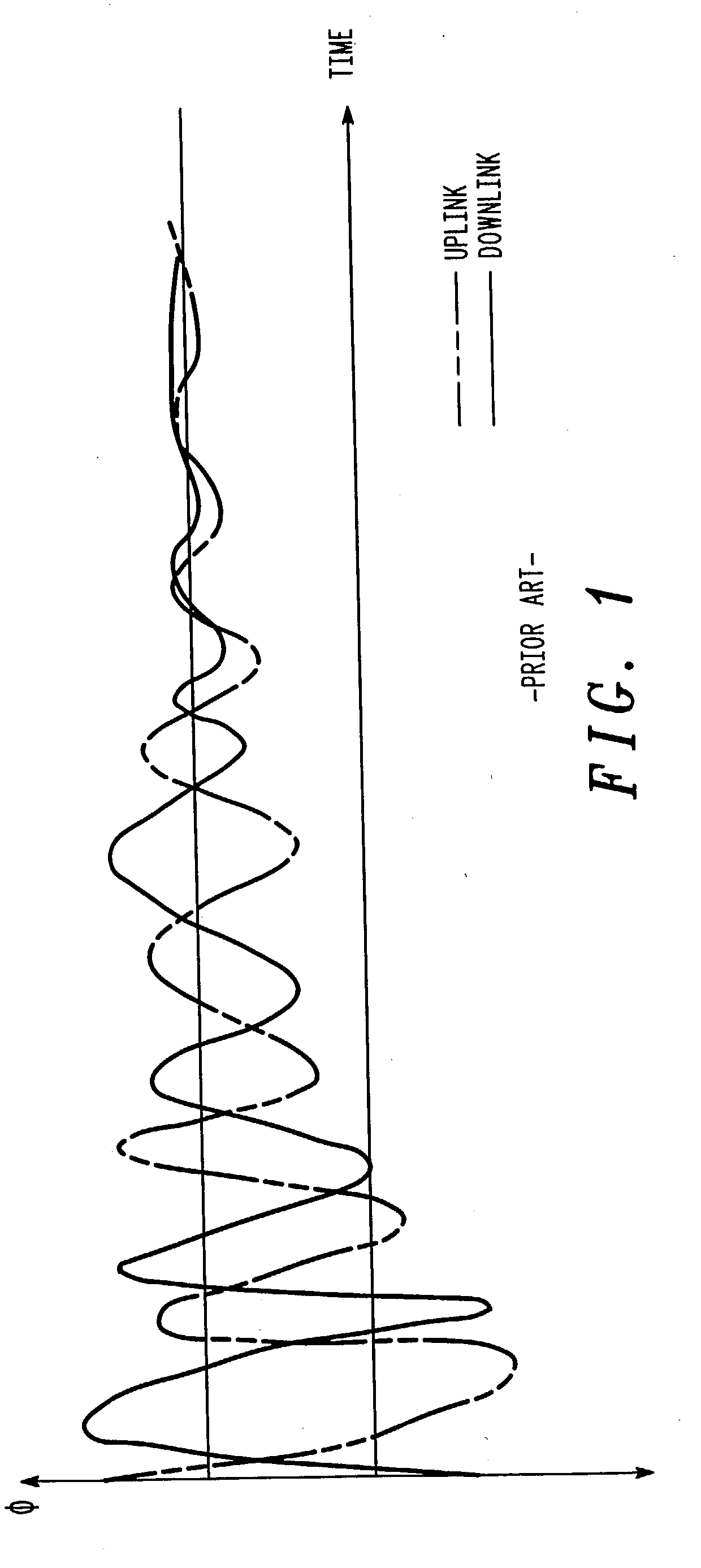
[0030] Turning to FIG. 1, there is shown a graphical representation of how directional estimates for uplink and downlink paths vary, and ultimately converge, with time. The x-axis (i.e. the abscissa) represents an averaging period and the y-axis (i.e. the ordinate) represents estimates of the uplink and downlink principal direction angle, .phi.. As can be seen, for very short averaging times (that is, the points towards the left hand side of the x-axis of the figure), the uplink and downlink directional estimates can be widely different. These differences arise from the different physical (and essentially instantaneous) propagation paths from the base station (i.e. the antenna array) to a subscriber unit and vice versa, with these differing propagation paths partially attributable to any difference in carrier frequency used to support the uplink and downlink channels. As either the averaging period or the time is increased (illustrated by movement towards the right-hand side of the ...


PUM


Abstract

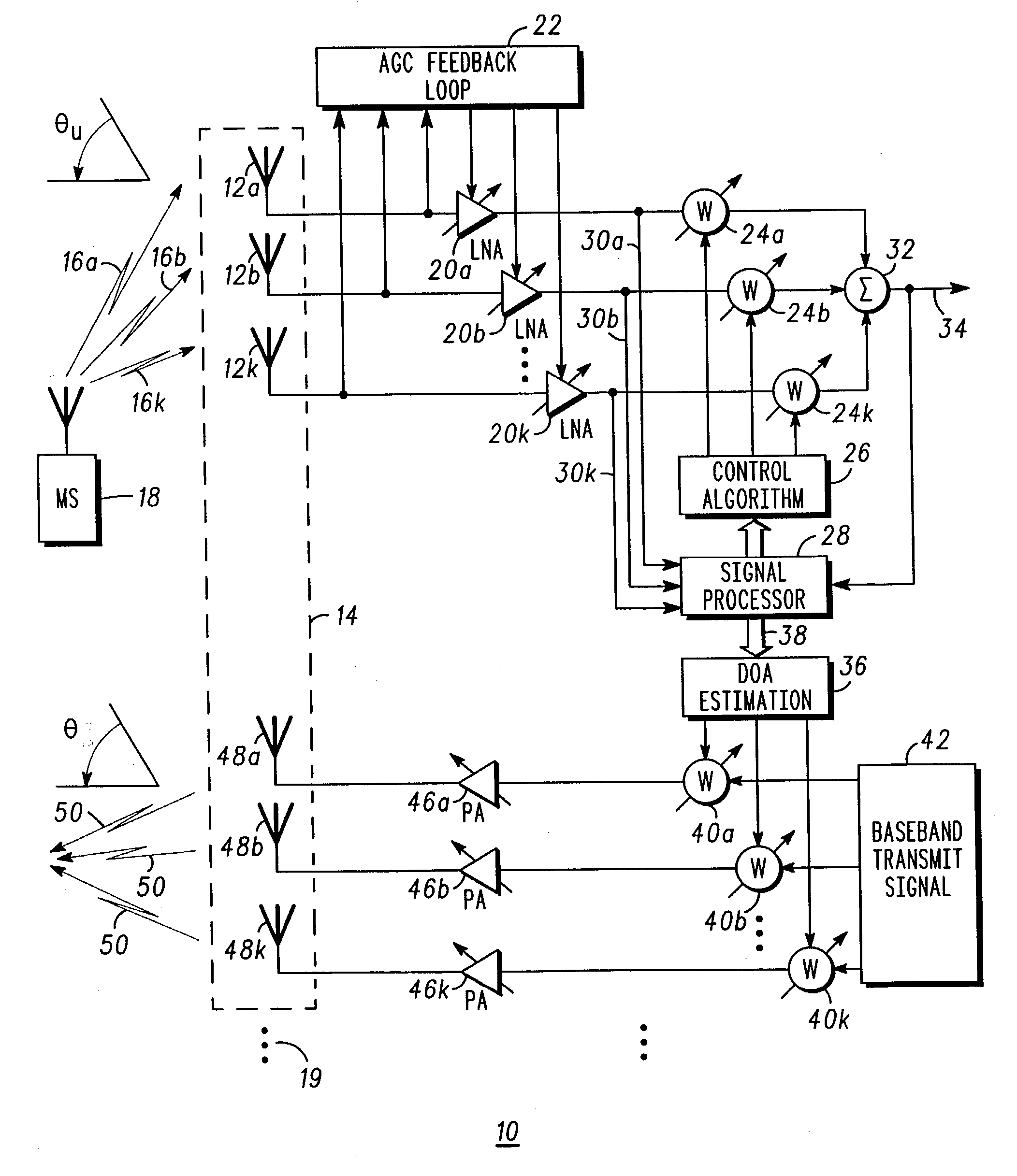
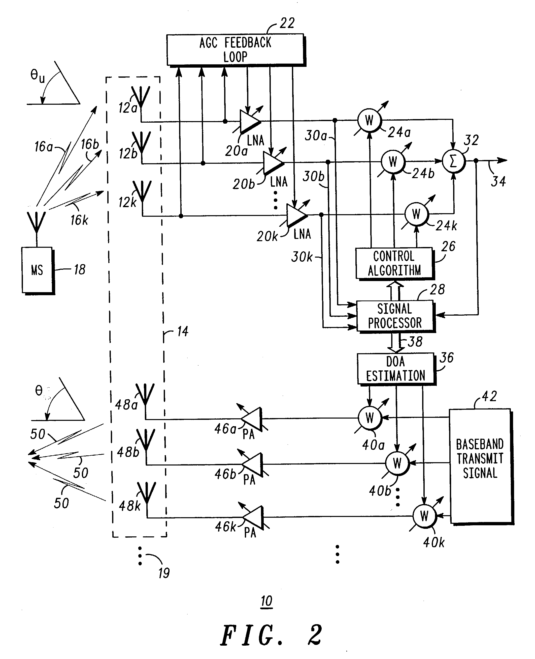
An adaptive antenna array (14) includes a muliplicity of antenna elements (12a-12k, 48a-48k) responsive to uplink communications (16a-16k) and arranged to support directional-orientated downlink communication to subscriber units (18). The adaptive antenna array (14) is operationally responsive to a signal processor (28) that co-operates with direction of arrival estimation logic (36) to assess an angle of arrival of uplink communications incident to the array. To avoid inter-cell interference, especially during early stages of a call, the signal processor operates to ensure that a wide area downlink beam (108) is provided for a downlink path to an addressed subscriber unit. With time and / or with reported (68,84) downlink quality of service (QoS) metrics, the signal processor (28) regulates (74, 92, 96) a width of the downlink beam by altering the number of antenna elements used to support the downlink beam, thereby altering the downlink beam aperture. Generally, with time, more antenna elements (92) are used and so the beam is narrowed, although in-call fluctuations in downlink quality of service are dynamically addressed by the signal processor (28) by either narrowing or broadening the width of the downlink beam by respectively switching antenna elements (12a-12k, 48a-48k) into (92) or out (96) of the adaptive antenna array (14), as shown in FIGS. 3a and 3b.

Description

BACKGROUND TO THE INVENTION[0001] This invention relates to an adaptive antenna array and a method of controlling the operation thereof. The present invention is particularly, but not exclusively, applicable to a method and apparatus for maximising Quality of Service (QoS) to a subscriber unit in a mobile wireless telecommunications system. More particularly, the present invention is applicable to operational use of an adaptive antenna array during the establishment of a connection to a subscriber unit, although it can be applied dynamically in an in-call scenario.SUMMARY OF THE PRIOR ART[0002] Adaptive antenna beam forming architectures provide a directional downlink beam based on information derived from uplink beam measurements. An attainable degree of prediction accuracy of a downlink estimate limits the capacity and frequency re-use that is achievable by any adaptive antenna network since an explicit downlink channel estimate is not available to the base station at which the an...

Claims


Application Information

Patent Timeline
IPC IPC(8): H04B7/10G01S3/46H01Q3/26H04B7/06H04B7/26
CPCG01S3/46H01Q3/2605H04B7/0602
Inventor OWEN, RAY
Owner GOOGLE TECH HLDG LLC
Learn More