Method of operating an active obstacle warning system

a technology of obstacle warning and active detection, which is applied in the direction of braking systems, instruments, and reradiation, etc., can solve the problems of unable to provide distance and relative speed information regarding obstacles, and unable to provide further information

Inactive Publication Date: 2004-09-23
CONTI TEMIC MICROELECTRONIC GMBH
View PDF4 Cites 15 Cited by
  • Summary
  • Abstract
  • Description
  • Claims
  • Application Information

AI Technical Summary

Benefits of technology

[0016] Such a power adaptation during a given respective measuring cycle achieves several advantages. First, for any particular operating situation, the emitting power can be reduced to the minimum power necessary for achieving the obstacle detection. Thereby, without diminishing the operational readiness or effectiveness, the dissipated power of the obstacle warning system can be reduced, for example by reducing the voltage supply, whereby as a result the operating temperature of the electronics is also reduced. As a result, the reduced operating temperature leads to an increased operating lifetime of the obstacle warning system, because its components are not loaded or taxed as significantly. Furthermore, if needed in a particular situation, the emitting power can be temporarily increased so as to enlarge the monitoring or detection range of the system, so as to detect and warn of obstacles at a greater distance and at an earlier time. Also thereby, the functionality and reliability of the obstacle warning system can be maintained in situations of particularly intensive sunshine or during high-speed driving. For these reasons, the inventive method is especially suitable for operating an obstacle warning system in a motor vehicle.

Problems solved by technology

A major disadvantage of these known systems is that they can only provide distance and relative speed information regarding the obstacle, and cannot provide any further information for identifying the obstacle.
Due to the transit time of the emitted light, the reception of the reflected light is somewhat staggered or time delayed.
However, these locations also suffer the problem that they are subject to a high operating temperature, due to strong heating, especially under conditions of direct sunshine heating the roof and the interior of the motor vehicle cabin.
As a result, the operating efficiency of these components is significantly reduced due to an increased noise proportion in the signal, especially in consideration of the relatively low signal-to-noise ratio that typically applies in this context.
This requires, however, that the surrounding environment does not change between successive measuring cycles, because otherwise, if the reflection characteristics or locations of obstacles change between successive measuring cycles, then the adjusted power level based on a reflection in a previous measuring cycle would no longer be suitable for the characteristics prevailing in the subsequent measuring cycle.
Of course, such a lack of change in the surrounding environment between successive measuring cycles cannot be ensured for an obstacle warning system in a moving motor vehicle.
As a result, the reduced operating temperature leads to an increased operating lifetime of the obstacle warning system, because its components are not loaded or taxed as significantly.

Method used


Image

  • Method of operating an active obstacle warning system
  • Method of operating an active obstacle warning system
  • Method of operating an active obstacle warning system

Examples


Embodiment Construction

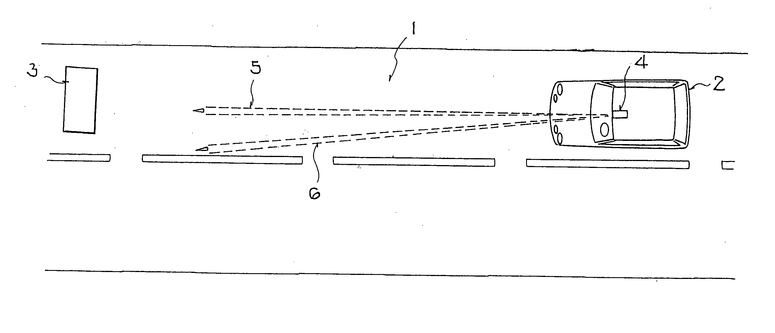
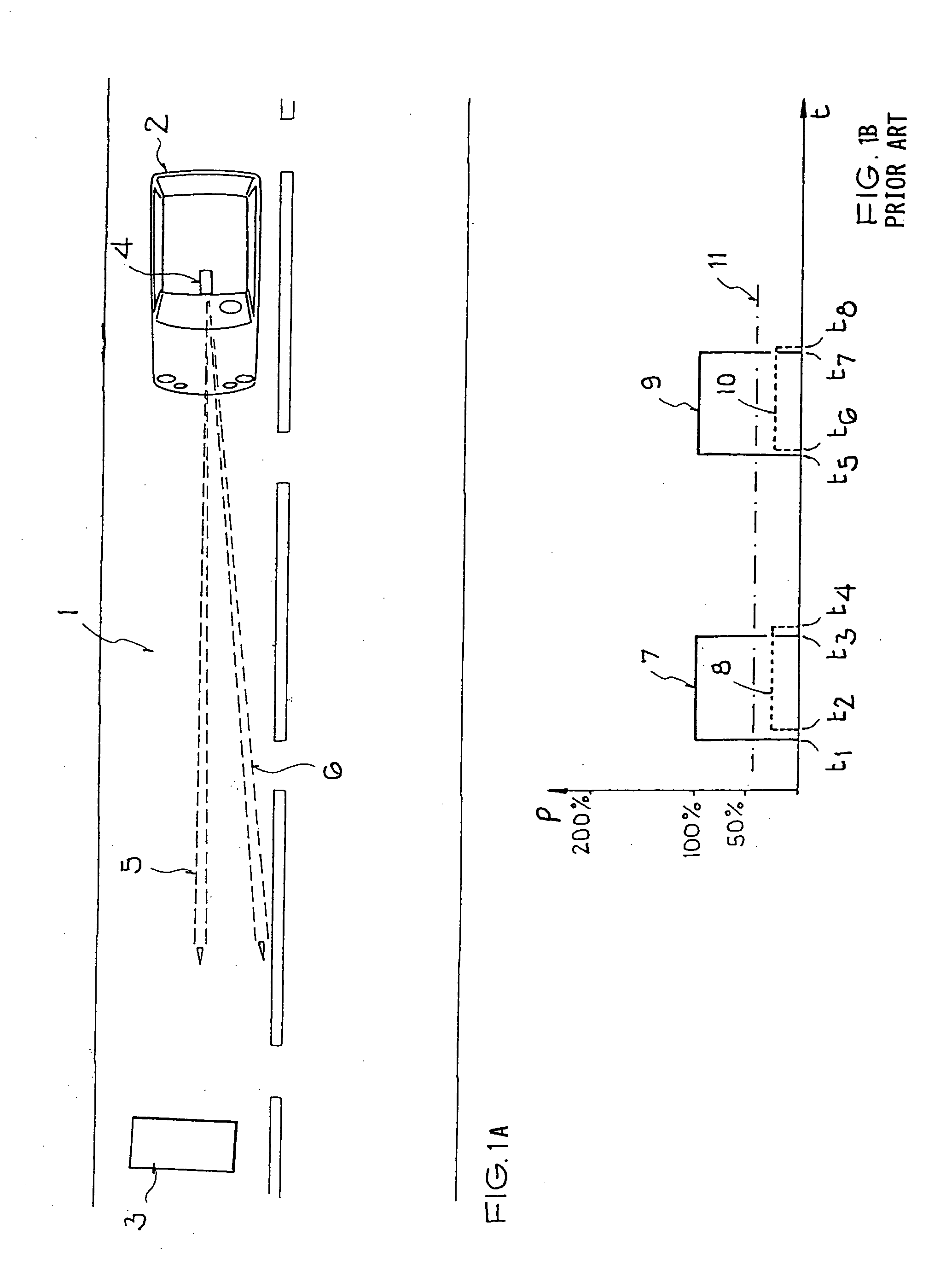
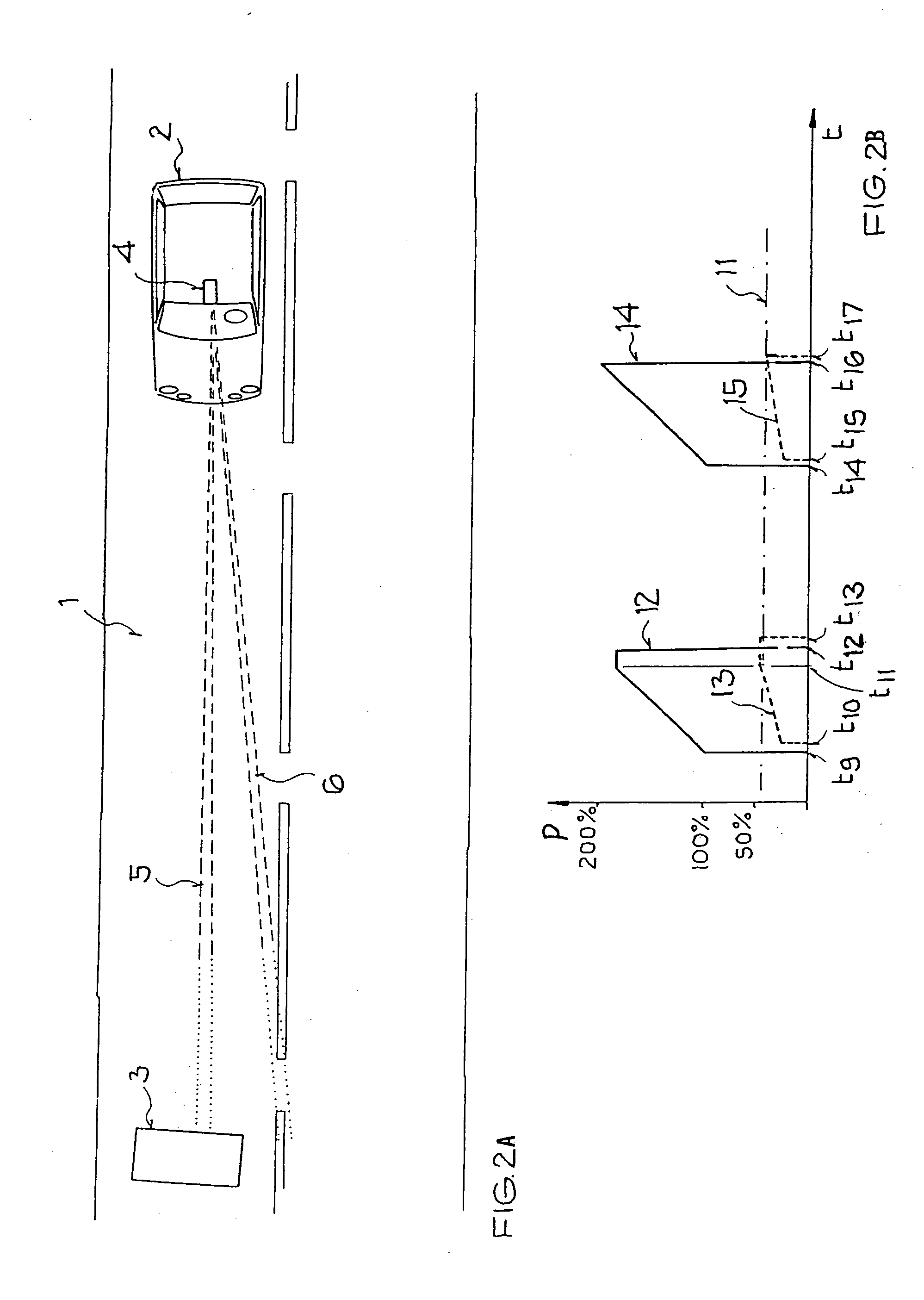
[0026] The top plan view of FIG. 1A schematically shows a motor vehicle 2 driving on a roadway 1 toward a stationary or moving obstacle 3. An obstacle warning system 4 is installed in the vehicle 2, and particularly preferably at an assembly point in the middle of the front of the ceiling or headliner of the vehicle 2. The obstacle warning system 4 emits electromagnetic waves forming at least two directed radiation lobes or beams 5 and 6 generally oriented in the forward driving direction of the vehicle 2. The obstacle warning system 4 may preferably comprise a photo mixing detector or photonic mixer device (PMD) sensor disclosed in the PCT Publication WO 99 / 60629 A1. Alternatively, the obstacle warning system 4 may comprise any other known device, components, or arrangement for detecting obstacles using at least one emitted radiation beam.

[0027] In any event, this system 4 serves to detect the obstacle 3, and measure the distance from the vehicle 2 to the obstacle 3 by evaluating a...


PUM


Abstract

From a prescribed starting value, the emitting power of an obstacle detection beam increases or decreases according to a prescribed function at a prescribed rate. The received signal reflected from an obstacle is compared to a prescribed threshold. Once the received reflected power rises or falls to the threshold, the emitting power is not further increased or decreased respectively, but is maintained constant. Thereby, consumed and dissipated power is reduced, unnecessary excessive power use is avoided, and the detection range of the obstacle detection beam is adapted to the prevailing situation.

Description

[0001] This application is a Continuation-In-Part under 35 U.S.C. .sctn.111(a) and .sctn.120 of PCT International Application PCT / DE02 / 02865, filed on Jul. 31, 2002, which designated the United States, and which was published in a language other than English. The entire disclosure of that PCT International Application is incorporated herein by reference.PRIORITY CLAIM[0002] Through the above identified PCT International Application, this application is based on and claims the priority under 35 U.S.C. .sctn.119 of German Patent Application 101 40 096.9, filed on Aug. 16, 2001. The entire disclosure of the German Priority Application is incorporated herein by reference.[0003] The invention relates to a method of detecting an obstacle and particularly a method of operating an active obstacle warning system that serves to detect the presence of, and measure a distance to, a target object generally called an obstacle herein.BACKGROUND INFORMATION[0004] In order to improve the safety of m...

Claims


Application Information

Patent Timeline
IPC IPC(8): G01S17/931B60W30/08B60W50/08G01S7/497G01S17/42G08G1/16
CPCB60W30/09B60W2050/143G08G1/16G01S17/42G01S17/936G01S7/497G08G1/165G08G1/166G01S17/931
Inventor BAERENWEILER, JOSEFFENDT, GUENTHERRIEDEL, HELMUT
Owner CONTI TEMIC MICROELECTRONIC GMBH
Why Eureka
Try Eureka