
Wireless antennas, networks, methods, software, and services

a technology of wireless antennas and networks, applied in the field of wireless antennas, networks, methods, software, and services, can solve the problems of limited capacity, time-consuming orientation and configuration processes, and high cost of network deployment, so as to reduce interference on links, and reduce the complexity and cost of nodes.

Inactive Publication Date: 2004-08-19
APPLE INC +1
View PDF6 Cites 162 Cited by
  • Summary
  • Abstract
  • Description
  • Claims
  • Application Information

AI Technical Summary

Benefits of technology

[0033] Advantageously, sharing a radio reduces complexity and cost of the node.
[0034] Advantageously, sharing a radio between the directional beams reduces the complexity and cost of the node. Furthermore, it may reduce interference on the links because the apparatus can only transmit or receive on any one beam at one time.
[0054] Advantageously, this reduces the physical size of the apparatus.
[0064] Advantageously, such services may be provided either more reliably, more quickly, more efficiently, or more cost-effectively over such networks.

Problems solved by technology

Deployment of such networks is a costly process and there is a very strong incentive to network builders and operators to minimise installation time and hence installation costs.
Nevertheless, known systems involve time-consuming orientation and configuration processes.
However, such arrangements exhibit both limited backhaul range between nodes and limited capacity.
A further problem with known wireless backhaul system employing omni-directional nodes is the forwarding problem in which a transmitting node prevents neighbouring nodes from transmitting due to contention for the channel (as, for example, with IEEE 802.11, RTS / CTS, etc.).

Method used


Image

  • Wireless antennas, networks, methods, software, and services
  • Wireless antennas, networks, methods, software, and services
  • Wireless antennas, networks, methods, software, and services

Examples


Embodiment Construction

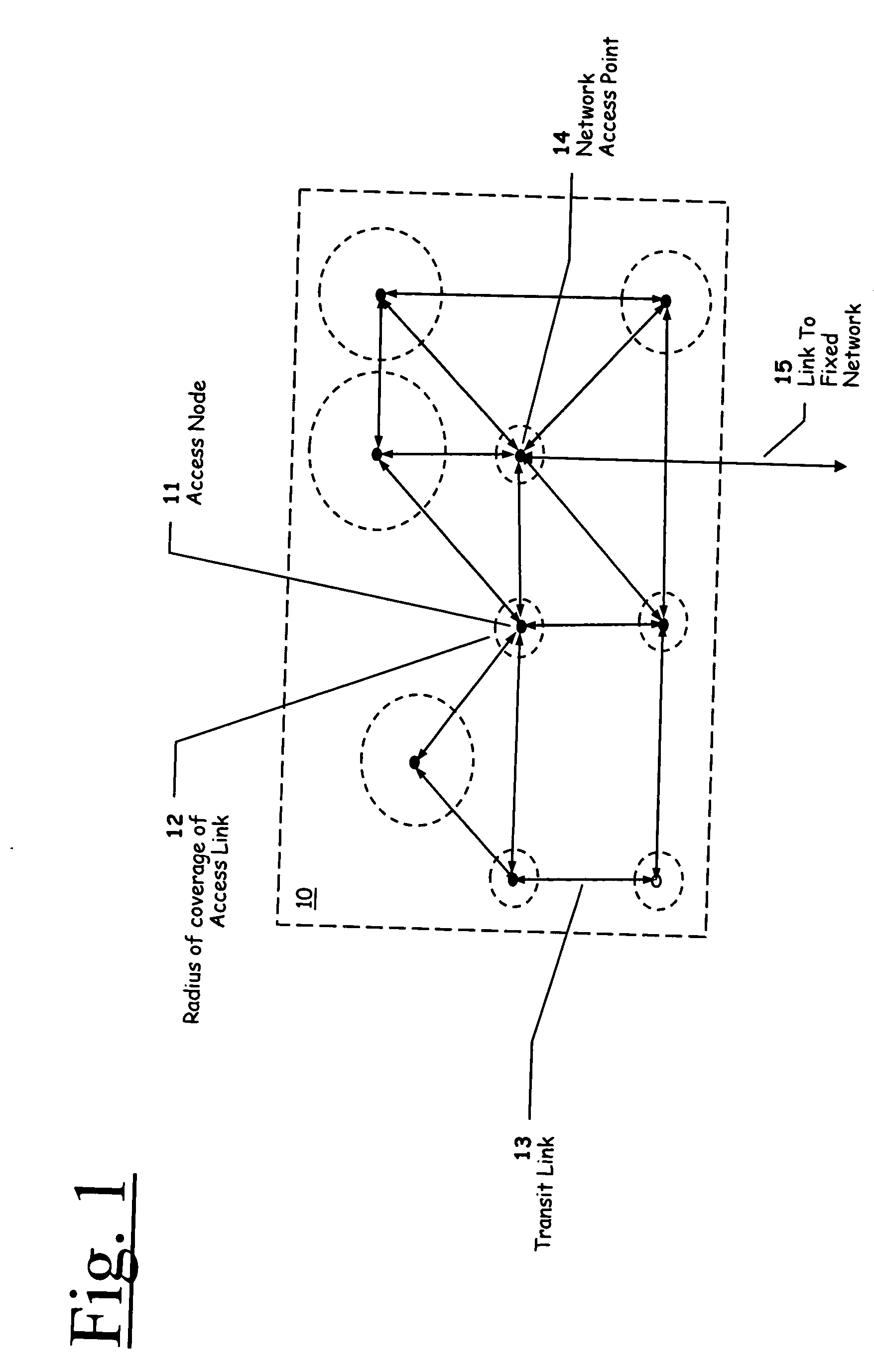
[0073] Referring first to FIG. 1, a Wireless Local Area Network (WLAN) Collector Network (WCN) 10 comprises a number of wireless access nodes 11 distributed across an area and coupled by backhaul (or transit) links 13. Such an access node may take the form of a wireless basestation, micro-cellular wireless base station, or any other form of wireless network access point. The nodes may be fully or partially meshed, form a ring, or have any other network connectivity as required. The nodes are connected by the backhaul links to at least one Network Access Point (NAP) 14 which provides a link 15 to the wired network. One NAP can serve many access nodes and the capacity per NAP depends on the number of channels available for the transit link and their reuse factor. The coverage area per NAP is unlimited, but the capacity per NAP will not be. For a viable system, the access nodes must be able to pass data to each other and hence to the NAP, and this is the function of the transit links. ...


PUM


Abstract

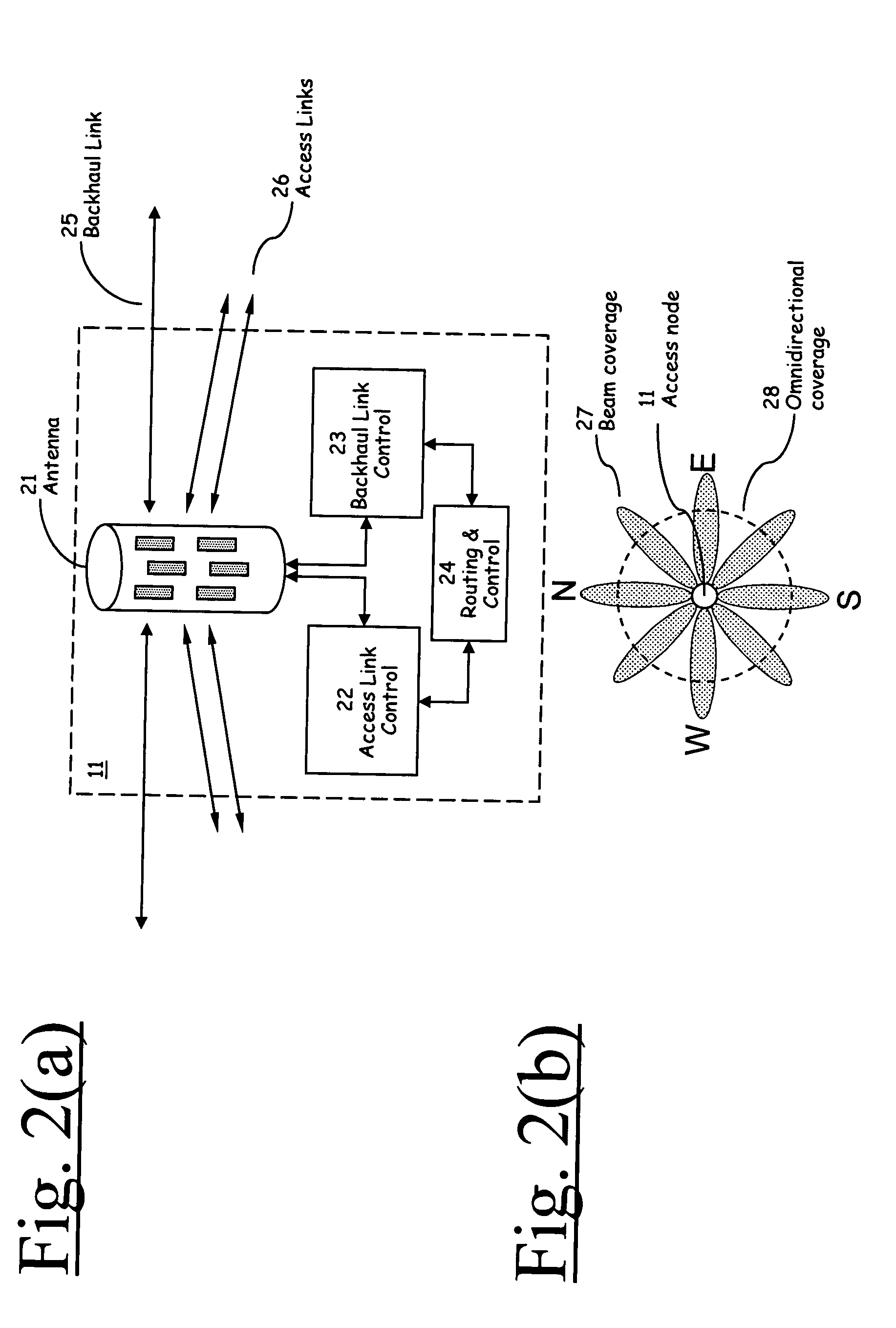
The invention is directed to a wireless network arrangement in which nodes comprise multi-faceted multi-beam antennas and in which wireless backhaul is provided using those multi-faceted multi-beam antennas. In particular, the invention is directed to a wireless communication node comprising: an antenna defining a first wireless coverage area and a second wireless coverage area. The first wireless coverage area extends in a first beam pattern and the second wireless coverage area extends in a second beam pattern and the second beam pattern comprises at least one directional beam having a direction which is variable. Associated apparatus, methods, programs, and subscriber services are also provided.

Description

[0001] This application is the full utility filing of U.S. provisional application No. 60 / 447,645 filed on Feb. 14, 2003, from which the present application claims priority and which is incorporated herein by reference.[0002] This patent application is related to the following Provisional patent applications filed in the U.S. Patent and Trademark Office, the disclosures of which are expressly incorporated herein by reference:[0003] U.S. Patent Application Serial No. 60 / 446,617 filed on Feb. 11, 2003 and entitled "System for Coordination of Multi Beam Transit Radio Links for a Distributed Wireless Access System" [15741][0004] U.S. Patent Application Serial No. 60 / 446,618 filed on Feb. 11, 2003 and entitled "Rendezvous Coordination of Beamed Transit Radio Links for a Distributed Multi-Hop Wireless Access System" [15743][0005] U.S. Patent Application Serial No. 60 / 446,619 filed on Feb. 11, 2003 and entitled "Distributed Multi-Beam Wireless System Capable of Node Discovery, Rediscovery ...

Claims


Application Information

Patent Timeline
Patent Type & Authority Applications(United States)
IPC IPC(8): H01Q1/24H01Q9/04H01Q21/00H01Q21/06H01Q21/20H01Q25/00H04L12/56H04W16/10H04W16/28
CPCH01Q1/246H01Q9/0435H01Q21/0087H04W16/28H01Q21/205H01Q25/00H04W16/10H01Q21/065
Inventor SMITH, MARTINWARD, CHRISBEVAN, DAVIDTEO, KOON HOOSMITH, ADRIAN
Owner APPLE INC
Learn More