Integrated micro electromechanical system encapsulation component and fabrication process of the component

a micro electromechanical and integrated technology, applied in the field of integrated micro electromechanical system encapsulation component and component fabrication process, can solve the problems of high cost of sealing stage, inability to guarantee a very good hermeticity of polymer, vacuum, etc., and achieve the effect of reducing the design constraints of mems and the fabrication cos

Inactive Publication Date: 2004-08-19
COMMISSARIAT A LENERGIE ATOMIQUE ET AUX ENERGIES ALTERNATIVES
View PDF0 Cites 10 Cited by
  • Summary
  • Abstract
  • Description
  • Claims
  • Application Information

AI Technical Summary

Benefits of technology

0017] The object of the invention is to overcome these drawbacks and more particularly to propose a process for fabricating integrated micro electromechanical systems minimizing the problems of collective fabrication, size, hermeticity, thermal expansion and solidity of the cover, while reducing the MEMS design constraints and fabrication cost.

Problems solved by technology

The sealing stage for example is very costly if it is performed on each individual chip after the latter have been cut out from the substrate.
None of the techniques known to date enables all these conditions to be met at the same time.
The major drawback is that it is impossible to guarantee a very good hermeticity with a polymer, notably to vacuum.
Polymers are furthermore not very resistant to aggressions from the environment.
It does however present the great drawback of leading to beads of very great width (a few hundreds of micrometers) which becomes unacceptable for large-scale distribution products.
But the width of the bead is linked to the glass paste deposition technique by silk screen process and it is therefore difficult to hope to reduce this width.
A large drawback is however that the cover must be deposited before the sacrificial layer for mechanical release of the MEMS is etched.
Release etching of the cover therefore has to be performed through holes in the cover, which is very complicated and requires a very special design of the MEMS.
This constraint greatly reduces the freedom of design of the MEMS itself.
Another drawback is the small thickness of the cover (a few micrometers), which in certain cases can be deformed due to the effect of the external pressure.

Method used


Image

  • Integrated micro electromechanical system encapsulation component and fabrication process of the component
  • Integrated micro electromechanical system encapsulation component and fabrication process of the component
  • Integrated micro electromechanical system encapsulation component and fabrication process of the component

Examples


Embodiment Construction

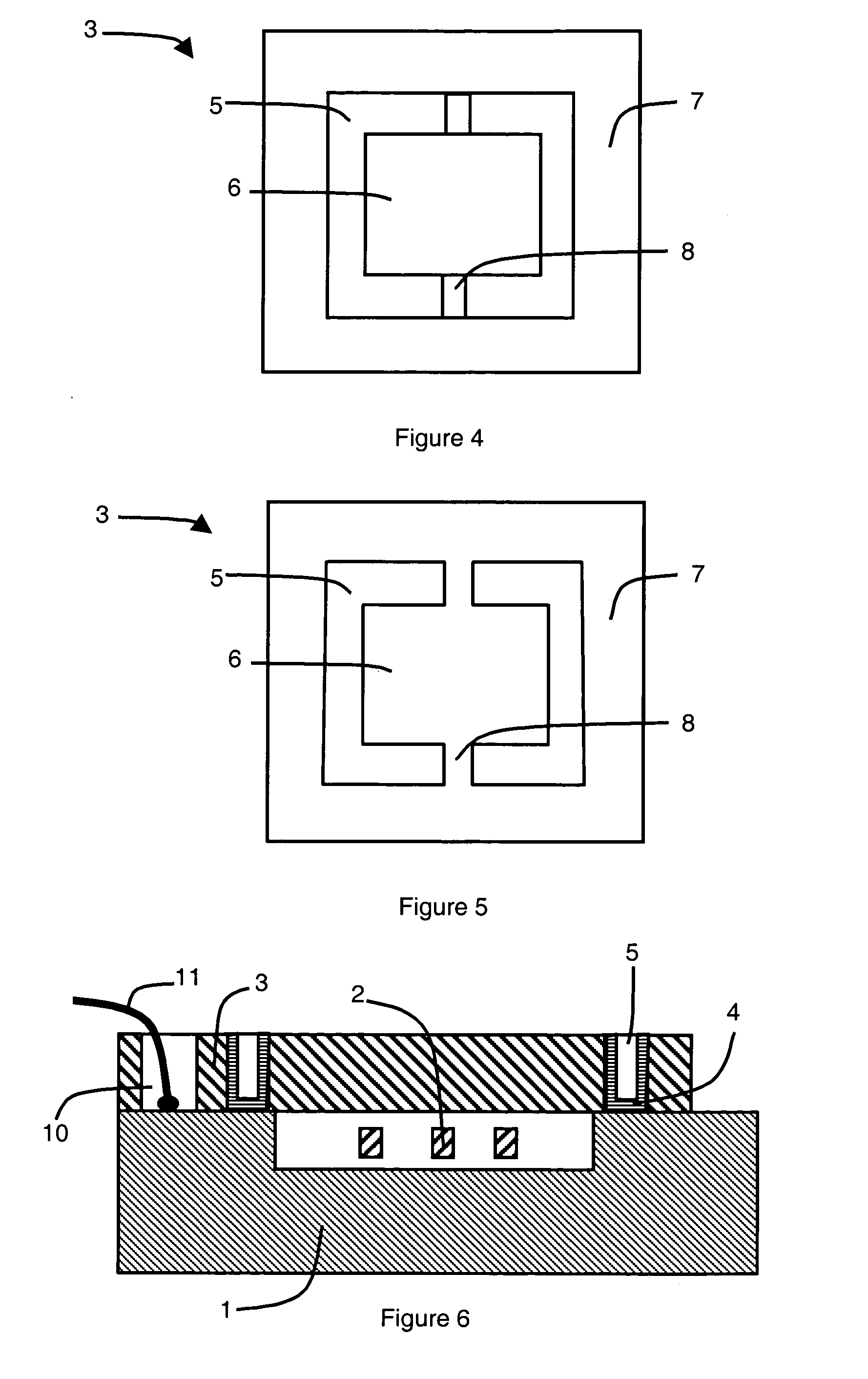
[0037] FIG. 2 represents a component comprising a substrate 1 and micro electromechanical systems 2 integrated in a cavity on the top face of the substrate 1. The cover 3, arranged with its rear face on the substrate 1, comprises at least one groove 5, for example annular, passing through the cover 3 and defining in the cover 3 a peripheral zone 7 and a central zone 6 completely covering the cavity.

[0038] To make the cavity hermetic, a sealing material 4 is deposited at least at the bottom of the groove 5. In FIG. 3, a layer of sealing material 4 is deposited on the front face of the cover 3, covering the whole of this front face, the walls and the bottom of the groove 5. The cover 3 can comprise additional grooves (not shown) in the central zone 6 enabling additional sealings to be performed on pads arranged in the cavity facing the additional groove.

[0039] The groove 5 is not necessarily annular. It may have internal and external perimeters that are square, circular or of more com...


PUM

PropertyMeasurementUnit
temperatureaaaaaaaaaa
electricallyaaaaaaaaaa
thicknessaaaaaaaaaa

Abstract

The component comprises micro electromechanical systems integrated in a cavity of a substrate and a cover sealed onto the substrate and designed to make the cavity hermetic. The cover comprises at least one groove passing through the cover and defining a central zone completely covering the cavity and a peripheral zone in the cover. A sealing material is deposited at least at the bottom of the groove. Fabrication of the component can comprise a first stage of making at least one groove in the cover, a second stage of bringing the substrate and cover into contact, and a third stage of sealing by depositing a sealing material in the bottom of the groove.

Description

[0001] The invention relates to a component for encapsulation of micro electromechanical systems integrated in a cavity, comprising a substrate wherein the cavity is formed, a cover presenting a front face and a rear face, arranged on the substrate, and means for sealing the cover onto the substrate designed to make the cavity hermetic.STATE OF THE ART[0002] The Micro ElectroMechanical Systems (MEMS) technology has undergone considerable development in the course of the last few years. The best known applications are accelerometers for airbags, gyrometers for navigation and radio-frequency and optical switches for telecoms.[0003] In order to reduce fabrication costs, it is sought to increasingly apply the principle of collective fabrication, on which the whole power of microtechnologies relies extensively. Thus, it is sought to fabricate the smallest chips possible so as to have as many of chips as possible on a single substrate.[0004] Collective fabrication is all the more interest...

Claims


Application Information

Patent Timeline
Patent Type & Authority Applications(United States)
IPC IPC(8): B81B7/00B81C1/00
CPCB81C2203/019B81C1/00269H01L2224/48463
Inventor DELAPIERRE, GILLES
Owner COMMISSARIAT A LENERGIE ATOMIQUE ET AUX ENERGIES ALTERNATIVES
Why Eureka
Try Eureka