
Interlabial pad

a technology of interlabial pads and pads, which is applied in the field of interlabial pads, can solve the problems of blood leakage, wearer discomfort, and the interlabial pads are not fixed or fixed to the underwear

Inactive Publication Date: 2004-07-29
UNI CHARM CORP
View PDF7 Cites 10 Cited by
  • Summary
  • Abstract
  • Description
  • Claims
  • Application Information

AI Technical Summary

Benefits of technology

[0012] The innermost area of the interlabial space, that is, the vestibule floor can easily change in accordance with the wearer's (user's) motion. For example, when the wearer's weight is allocated downward (from the vestibule floor toward the end of the labia) with such motions as the wearer sitting down on a chair, the vestibule floor changes in form by being forced down. When the wearer's legs are moving back and forth alternatively in walking or other motions, the vestibule floor changes in form to flex, adjusting from right and left due to the pressure from the thighs.
[0058] The method will make it easy to adjust the shape flexibility of the interlabial pad. If the wearer uses this method, the shape of the interlabial pad is easily adjusted.

Problems solved by technology

Moreover, as for the tampon, there have been great efforts made for relieving the foreign feeling and the discomfort when wearing the sanitary products as well as intervaginal wearing trouble due to the nature of those products.
If the interlabial pad cannot follow the body motions and falls from the wearer's interlabial space, the resulting leak of blood is a significant problem.
However, unlike usual sanitary napkins, the interlabial pad is not fixed to the underwear or fixed by insertion like tampons.
Therefore, with the wearer's body motion, slips between the interlabial absorbent structure (equivalent to the structure of the interiabial pad whose absorbent pad is joined by the isthmus) and the labia may tend to occur, which may make the wearer feel discomfort.
Therefore, it is difficult for the isthmus to change its form to follow the changes in form of the vestibule floor described above, which may cause the wearer to sense the stiffness of the isthmus, that is, a feeling of discomfort with the wearer's body motions.
However, though the absorbent body, which is mainly responsible for maintaining the shape of the interlabial pad, is flexible, the capability of the absorbent body is limited as the absorbent body is relatively thick.

Method used


Image

  • Interlabial pad
  • Interlabial pad
  • Interlabial pad

Examples


Embodiment Construction

[0080] Next, the embodiments of the interlabial pad in the present invention will be described with reference to the figures.

[0081] [Basic Interlabial Pad]

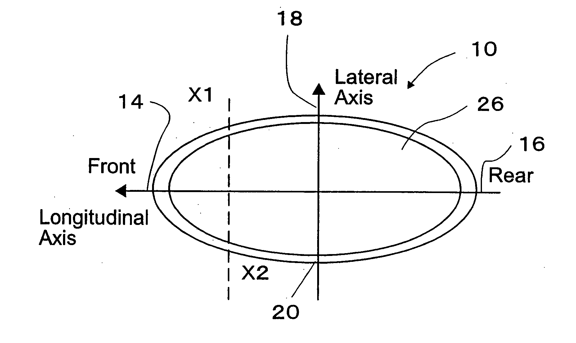
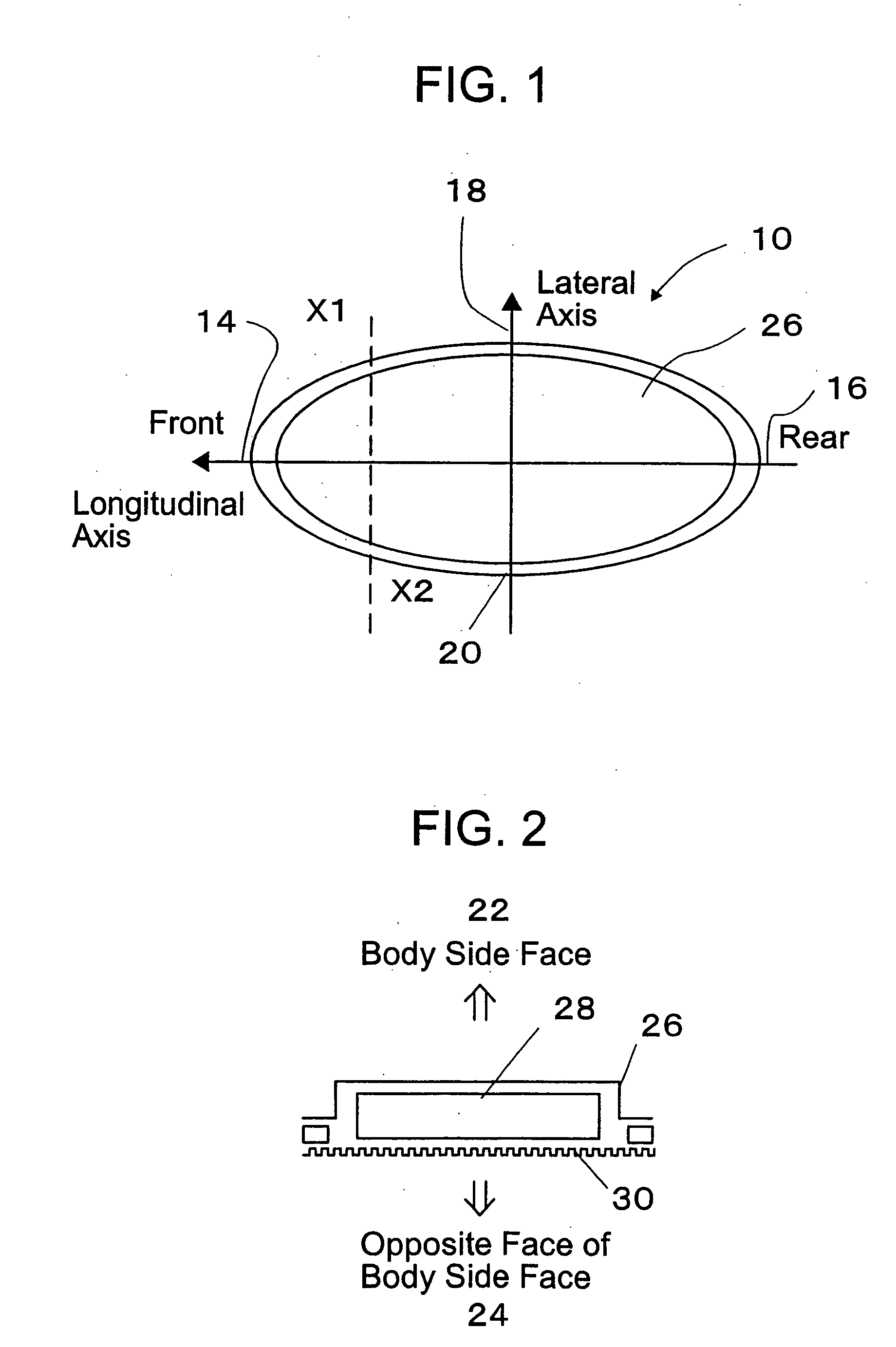
[0082] FIG. 1 shows a schematic plan view of an interlabial pad 10. An interlabial pad of the embodiment essentially has a shape which is elongated longitudinally, that is, an elliptical shape having the major axis of front 14 to rear 16 on the longitudinal axis (X-axis), and the minor axis of right 18 to left 20 on the lateral axis (Y-axis). However, the shape of the product is not necessarily confined, as long as the shapes are suitable for the labial area and allow right and left phase shifts during use, such as elliptical shape, gourd shape and tear drop shape.

[0083] FIG. 2 shows a schematic cross-sectional view taken along line X1-X2 of FIG. 1. The interlabial pad 10 comprises a liquid permeable surface side sheet 26 contacting the wearer's body side surface 22, that is, the inner walls of labia; a permeable or non permeable ...


PUM

PropertyMeasurementUnit
thicknessaaaaaaaaaa
lengthaaaaaaaaaa
distanceaaaaaaaaaa

Abstract

The present invention relates to an interlabial pad that is worn by female wearers, placed in intimate contact and supported between the labia, which provides an interlabial pad that causes no discomfort to the female wearer in the body motions of the wearer. The interlabial pad of the present invention is characterized by having bending elements which allows the interlabial pad to follow the changes in form flexibly even when a force is exerted on the interlabial pad by the wearer's body motion.

Description

[0001] This application is a Continuation of International Application No. PCT / JP02 / 04889 filed May 21, 2002, which application published in Japanese on Nov. 28, 2002 as WO 02 / 094153 A1 under PCT Article 21(2).[0002] 1. Technical Field[0003] The present invention relates to an interlabial pad that is worn by female wearers, placed in intimate contact and supported between the labia.[0004] 2. Background Art[0005] Conventionally, a sanitary napkin and a tampon are used generally as female sanitary products. Here, there have been great efforts made to prevent the leak of blood from gap caused by poor adhesion near the ostium vaginae as for the sanitary napkin. Moreover, as for the tampon, there have been great efforts made for relieving the foreign feeling and the discomfort when wearing the sanitary products as well as intervaginal wearing trouble due to the nature of those products.[0006] Under such situation, sanitary products of the interlabial pad have attracted attention as a san...

Claims


Application Information

Patent Timeline
Patent Type & Authority Applications(United States)
IPC IPC(8): A61F13/15A61F13/82A61F15/00
CPCA61F13/15211A61F2013/8497A61F13/15577A61F13/4702A61F13/4704A61F13/47209A61F13/474A61F13/534A61F13/535A61F13/55165A61F13/82A61F13/8405A61F15/001A61F2013/15235A61F2013/15357A61F2013/53445A61F13/15252A61F13/15
Inventor MIZUTANI, SATOSHIYAMAKI, KOICHINODA, YUKITOKUMOTO, MEGUMISAKAI, AKANE
Owner UNI CHARM CORP
Learn More