
VHF/UHF broadband high power amplifier module

a high-power amplifier and broadband technology, applied in the direction of amplifier modifications, push-pull amplifiers, phase splitters, etc., can solve the problems of circuit design that cannot be used in y or s parameters, circuits may only be able to reach 1 to 2 times the bandwidth of their operation, and the manual of the manufacturer of rf power transistors may not provide s parameters in their products,

Inactive Publication Date: 2004-07-08
CHEN SOU BIN
View PDF1 Cites 13 Cited by
  • Summary
  • Abstract
  • Description
  • Claims
  • Application Information

AI Technical Summary

Benefits of technology

[0023] Still, another object of this invention is to provide a broad-band high power module at a reduced cost and capable of efficient heat dissipation irrespective of the bulky broadband high power system structure.
[0024] Still further, another object of the present invention is to provide an electronic circuit configured to provide said broadband high power performance for broadband high power amplifier module, which may be used in both commercial and military applications.

Problems solved by technology

Because broadband high power amplifier module is a key component of a broadband rapid response power amplifier, a broadband high power amplifier module is an important and intricate part of communication jamming electronics.
As for large signal output power amplifiers, the manufacturer of RF power transistor may not provide S parameter in their product's manual.
Although some manufacturers would provide some products with S parameter, these products may well not fulfill the design requirements, and therefore these large signal output power amplifier may well not be able to use Y or S parameter for circuit design.
However these circuits may only be able to reach 1 to 2 times as large as its operational bandwidth.

Method used


Image

  • VHF/UHF broadband high power amplifier module
  • VHF/UHF broadband high power amplifier module
  • VHF/UHF broadband high power amplifier module

Examples


Embodiment Construction

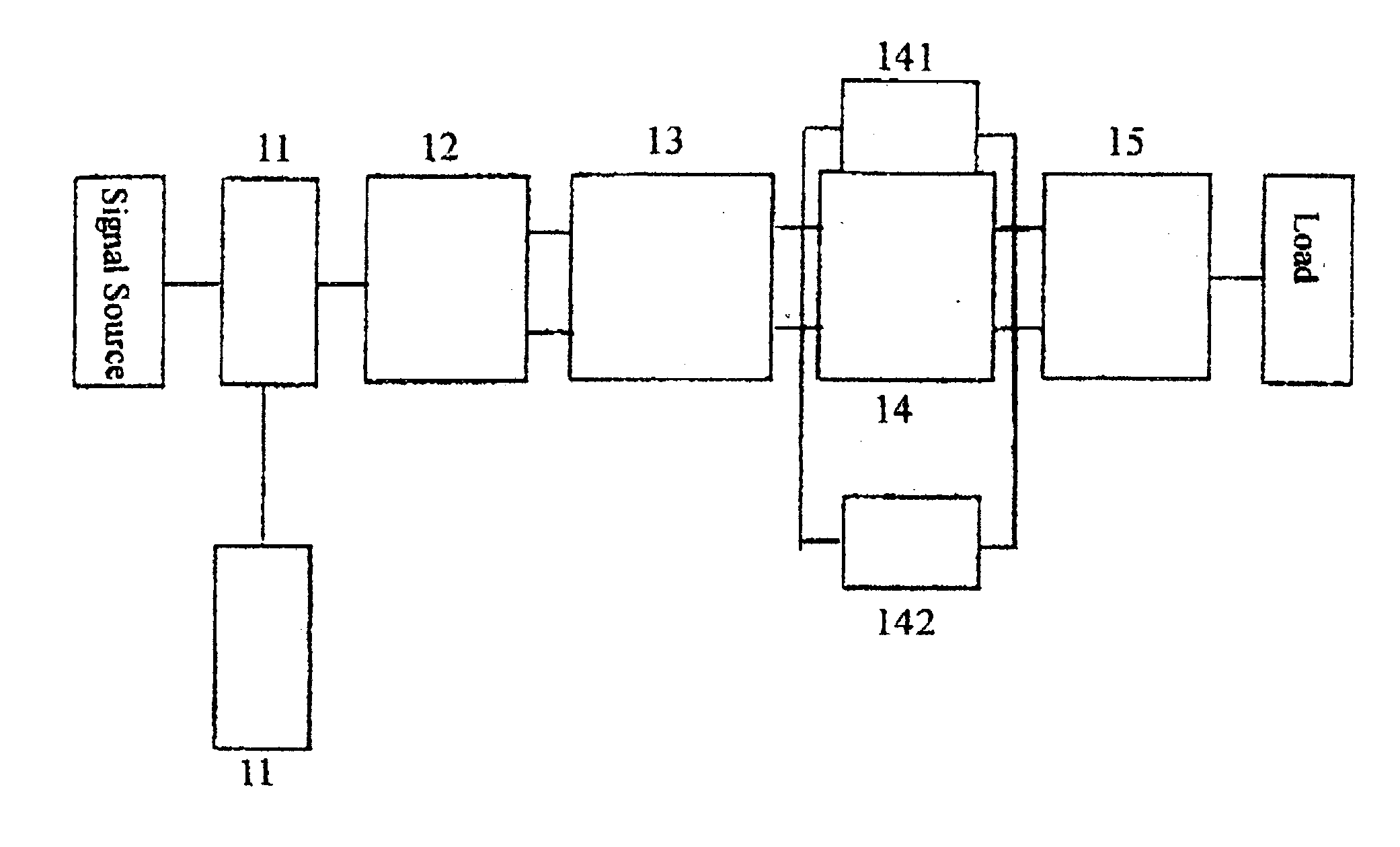
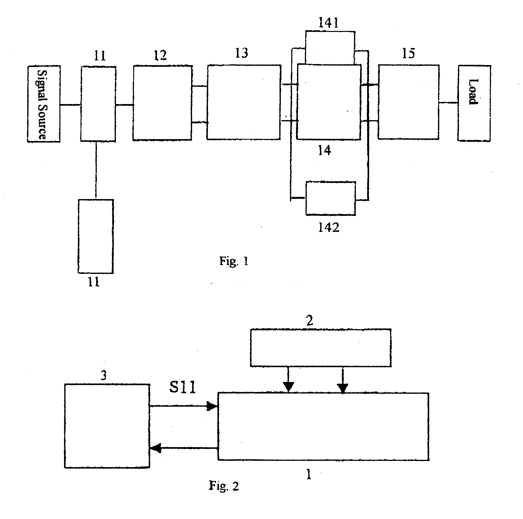
[0032] FIG. 1 shows a block diagram of the VHF / UHF broadband high power amplifier module of the present invention consisting of a broad / narrow band frequency attenuator 11, a micro strip line circuit 13, a push-pull power transistor 14 and a broadband matcher 15, wherein said broad / narrow band frequency attenuator 11 is used to attenuate input signal source for improving stability of the VSWR and the gain flatness. It is preferred to use T type R, L, C serial circuit, as the attenuation quantity is inversely proportional to the operational frequency.

[0033] Still referring to FIG. 1, the broadband matcher 12 is coupled to the broad / narrow band frequency attenuator 11 to perform impedance matching for the attenuated signal source he micro strip line circuit 13 is coupled to the broadband matcher 12 to perform impedance transformation by boosting 3 .OMEGA. input impedance to 12.5 .OMEGA. in three stages and then subsequently raising the input impedance to 50 .OMEGA. through a broadband...


PUM


Abstract

A VHF / UHF broadband high power amplifier module of the present invention comprising: a broad / narrow band attenuator for attenuating input signal source; a broadband matcher coupled to said broad / narrow band attenuator for impedance matching said attenuated input signal source; a micro-strip line circuit coupled to said broad band matcher to perform first impedance transformation; a power transistor coupled to said micro-strip line circuit to perform AB class push pull amplification; a broad band matcher coupled to said power transistor and a load to perform second impedance transformation of said load; and said transformed low impedance to become the load of said Rf power transistor.

Description

BACKGROUD OF INVENTION[0001] 1. Field of the Invention[0002] The present invention relates to a VHF / UHF broadband high power amplifier module. More specifically, the present invention relates to a VHF / UHF broadband high power push-pull amplifier module design with 100 MHz-500 MHz 100 W output power module, and with a whole bandwidth having 100 W output power and a 12 dB gain at 500 MHz.[0003] 2. Description of Related Art[0004] Now a days radio communication technology has become more popular and widely used in various fields. However, for radio communication to get across to remote site power amplifiers are needed to send information to respective receivers. Various power amplifiers are used in commercial and military applications. This is especially true in the electronic communication warfare business. Electronic communication warfare has very important role to play in modern military operations, and the communication jamming electronics of electronic communication warfare requir...

Claims


Application Information

Patent Timeline
Patent Type & Authority Applications(United States)
IPC IPC(8): H03F1/08H03F1/48H03F1/56H03F3/26H03F3/60
CPCH03F1/08H03F1/486H03F3/60H03F3/26H03F1/56
Inventor CHEN, SOU-BIN
Owner CHEN SOU BIN
Learn More