Plasma reactor with high selectivity and reduced damage

a plasma processing reactor and high selectivity technology, applied in the direction of electrical equipment, basic electric elements, electric discharge tubes, etc., can solve the problems of charge build-up, breakdown and damage of thin oxide films, and many types of structures become much more subject to damag

Inactive Publication Date: 2004-06-17
KELLER JOHN H
View PDF3 Cites 4 Cited by
  • Summary
  • Abstract
  • Description
  • Claims
  • Application Information

AI Technical Summary

Problems solved by technology

Further, many types of structures become much more subject to damage during manufacturing processes.
Moreover, manufacturing processes increasingly rely upon selectivity between materials to form structures of sub-lithographic dimensions and to maintain independence between processes so that results of particular processes are confined to the intended structures.
Such a thin structure is particularly subject to damage from receiving charge build-up thereon which can cause breakdown and damage to the thin oxide film, particularly from charged particles produced in plasma processes such as reactive ion etching (RIE) of other structures.
Such charge build-up can occur through several mechanisms such as insufficiently complete neutralization of surface charge, non-uniform plasma density and potential, electrons diffusing out of the plasma when the electron temperature is too high and collecting on the top surface of high aspect ratio structures and/or excessive RF bias on the workpiece.
Unfortunately, plasma processes have such advantages in terms of predictability, repeatability and throughput that they remain the process of choice notwithstanding the increased likelihood of oxide damage.
Such regulation of plasma conditions is often inconsistent with economically acceptable levels of plasma reactor throughput.
However, particle interactions within a plasma are very complex and the production of some desirable plasma conditions are often linked with other undesirable conditions in various known plasma processes such that the desirable condition cannot be independently achieved.
For example, known RF plasma systems do not produce sufficient plasma density to support production throughput levels without becoming a direct source of oxide and device damage.
Further, these systems produce an excessive ele

Method used


Image

  • Plasma reactor with high selectivity and reduced damage
  • Plasma reactor with high selectivity and reduced damage
  • Plasma reactor with high selectivity and reduced damage

Examples


Embodiment Construction

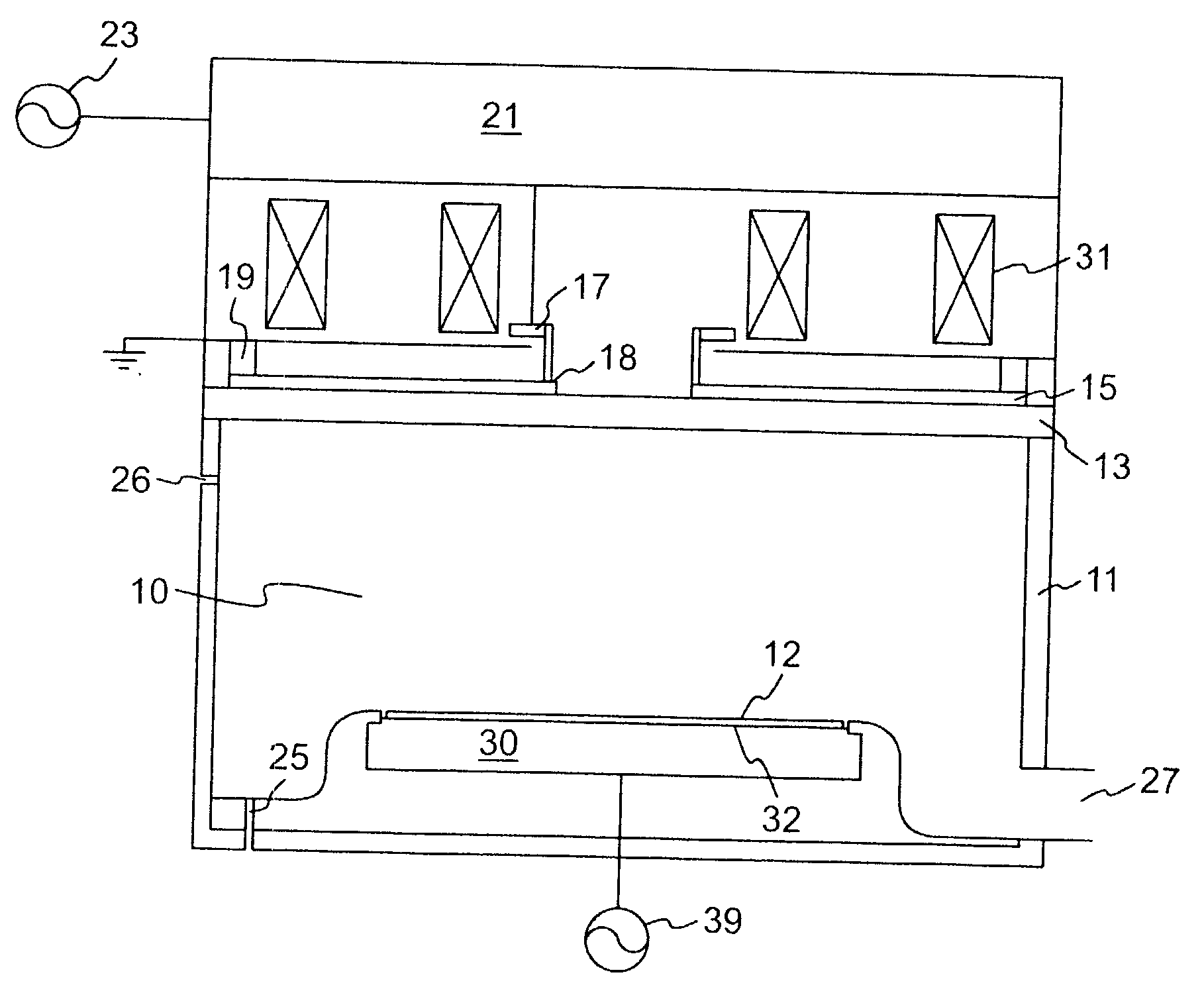
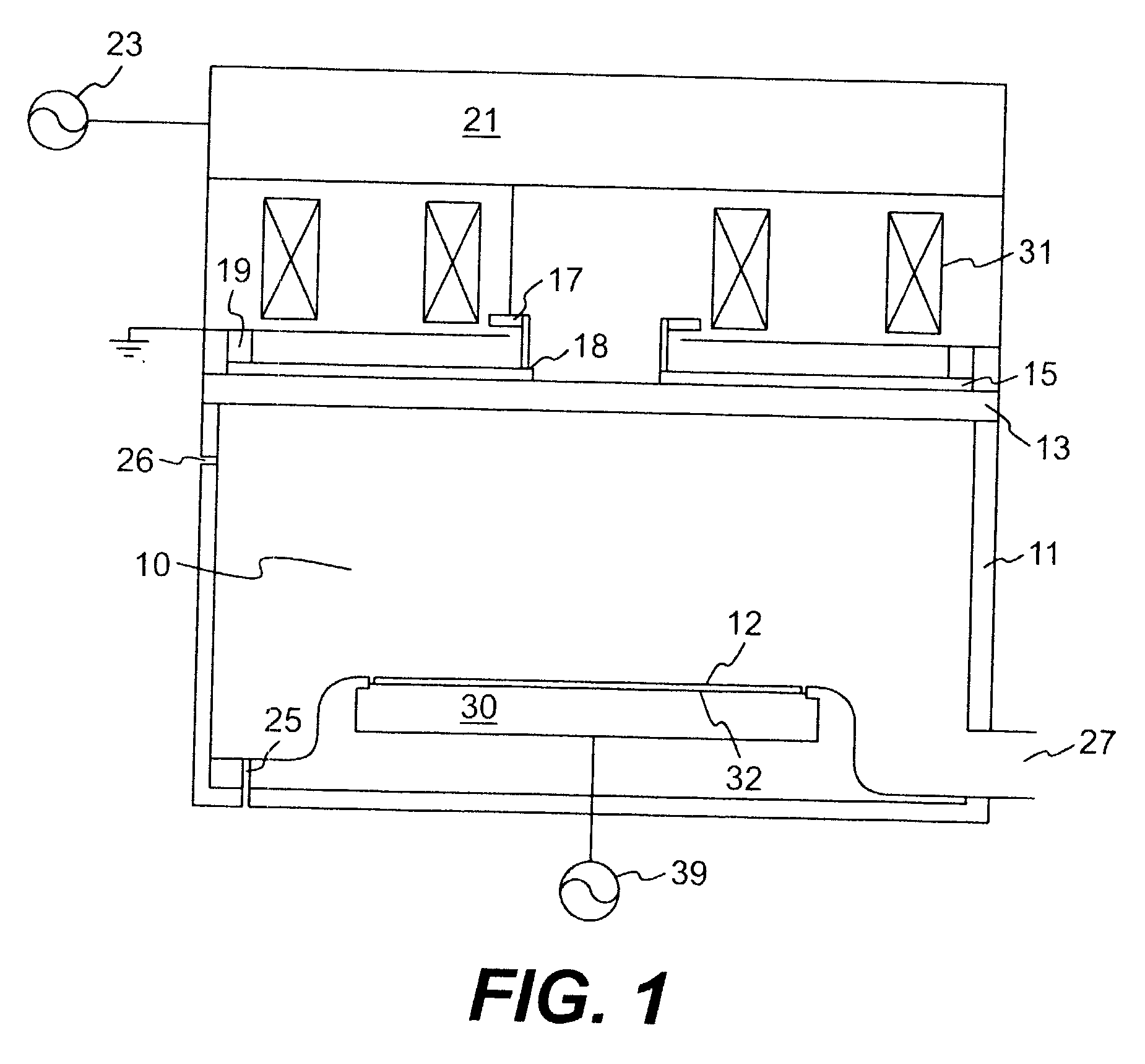
[0028] Referring now to the drawings, and more particularly to FIG. 1, there is shown a cross-sectional side view of a reactor vessel in accordance with the invention. It should be understood that many of the elements of the plasma reactor vessel are common to known plasma reactor vessels and are well-understood by those skilled in the art. Details of the plasma reactor vessel and known elements thereof are not critical to the practice of the invention and will be briefly summarized. This particular embodiment of the invention is suitable for use at pressures of above 10 mTorr characteristic of older plasma reactor vessels having lower pumping speed than current reactor vessel arrangements but can also be used at lower pressures as well.

[0029] Specifically, the reactor vessel includes walls 11 defining a chamber or cavity 10. A vacuum pump is connected to outlet duct 27 to maintain a high level of vacuum in the cavity 10 while reactant / etchant gas is supplied through one or more inl...


PUM

PropertyMeasurementUnit
Poweraaaaaaaaaa
Magnetic fieldaaaaaaaaaa
Densityaaaaaaaaaa

Abstract

Uniformity of plasma density is enhanced at high plasma density and with reduced gas cracking and/or without electron charging of a workpiece by limiting coupling of voltages to the plasma and returning a majority of RF current to elements of an antenna driven with different phases of a VHF/UHF signal and/or providing a magnetic filter which separates a hot plasma region from a cold plasma region along a side of the chamber and further provides a preferential drift path between the hot and cold plasma regions. The magnetic field structure of the magnetic filter is preferably closed at one end or fully closed to surround the plasma. Additional magnetic elements limit the transverse field at the surface of a workpiece to less than 10 Gauss. Either or both of the antenna and the magnetic filter can be retrofitted to existing plasma reactor vessels and improve the performance and throughput thereof.

Description

[0001] 1. Field of the Invention[0002] The present invention generally relates to radio frequency plasma processing reactors, especially as used in semiconductor processing and, more particularly, to high throughput reactors capable of achieving high etch rates with high material selectivity with reduced damage to extremely thin layers of material.[0003] 2. Description of the Prior Art[0004] Processing of semiconductor materials to form integrated circuits has become highly sophisticated and is presently capable of producing very high performance circuit elements at very small feature size regimes and extremely high integration density. As devices are scaled to small sizes manufacturing and process tolerances are also reduced and structures formed must be of increasingly exact dimensions in order to provide desired electrical characteristics. Further, many types of structures become much more subject to damage during manufacturing processes. Moreover, manufacturing processes increas...

Claims


Application Information

Patent Timeline
IPC IPC(8): H01J37/32H01L21/306
CPCH01J37/32091H01J37/3266H01J37/32623H01J37/3211
Inventor KELLER, JOHN H.
Owner KELLER JOHN H
Why Eureka
Try Eureka