
Centerline and tree branch skeleton determination for virtual objects

a virtual object and branch branch technology, applied in the field of computer-based three-dimensional visualization, can solve the problems of new challenge, disadvantage of computational cost, and high cos

Inactive Publication Date: 2004-06-10
THE RES FOUND OF STATE UNIV OF NEW YORK
View PDF0 Cites 63 Cited by
  • Summary
  • Abstract
  • Description
  • Claims
  • Application Information

AI Technical Summary

Benefits of technology

[0010] It is an object of the present invention to provide an improved method for generating a centerline, and where applicable a skeleton, of a virtual object.
[0012] The method preferably includes steps to initially identify points which are near the centerline of the object. In this case, the steps of determining a penalty value and determining a path described above can be performed only on those points which are near the centerline. This reduces the dataset which is to be processed thereby improving processing cost and speed.

Problems solved by technology

However, because of the high level of manual intervention involved in this technique, it is expensive and generally not preferred.
While this technique has generally proven effective at determining a centerline in objects such as the colon, it has the disadvantage of being computationally expensive.
In addition, with certain geometry's, the centerline that is determined by topological thinning is not always the centerline which would be intuitively desired.
Although a number of techniques are known for generating a skeleton of an object, each of the known techniques have inherent drawbacks.
This is accomplished due to the fact that virtual reality and computer graphics allow the virtual camera to view from any arbitrary viewpoint and with any arbitrary view-direction, while optical colonoscopy is limited to a path in one direction along the colon (due to the fact that the optical camera is placed at the end of a probe with limited mobility).
However, with the flexibility that is provided by virtual examination comes a new challenge.
Specifically, the difficulty in following orientation changes.
The colon is a very tortuous organ, and, as a result, when following along the colon in 3D users can become disoriented.
This risk is especially present when the user veers off the centerline and examines a structure close to the colon wall.

Method used


Image

  • Centerline and tree branch skeleton determination for virtual objects
  • Centerline and tree branch skeleton determination for virtual objects
  • Centerline and tree branch skeleton determination for virtual objects

Examples


Embodiment Construction

[0028] The present invention provides an improved and computationally efficient method of automatically generating a centerline in a lumen or a skeleton in a more complex object. The method uses the concept of penalized distance fields to augment known shortest path algorithms, such as the Dijkstra shortest path. The examples referred to are generally in the context of medical examination, such as virtual colonoscopy, but are applicable to any application of computer based virtual navigation.

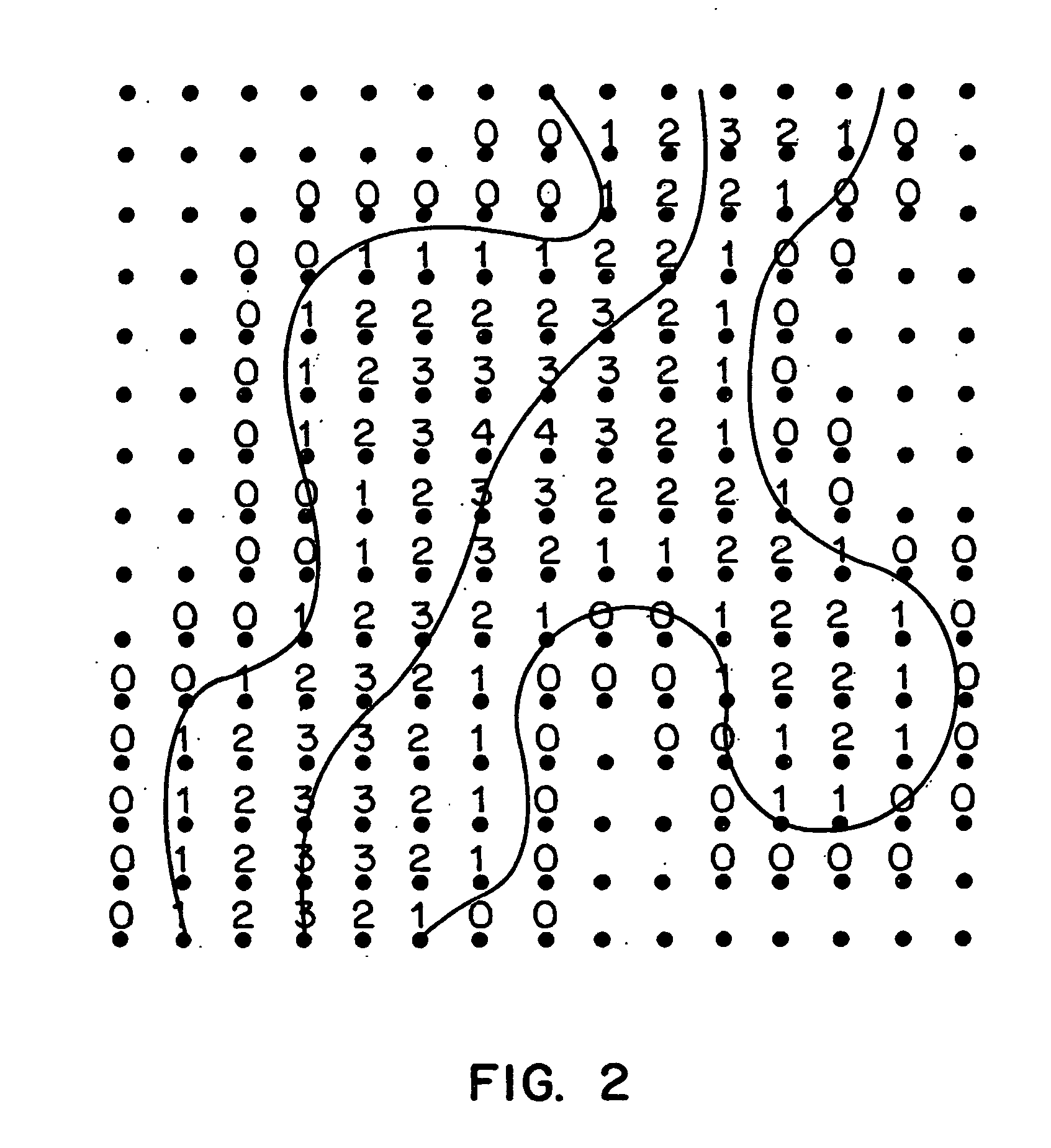
[0029] As noted above, a problem with the known Dijkstra shortest path algorithm is evident when the path through the object turns sharply. In such a case, without some form of embellishment or modification, the Dijkstra shortest path will tend to hug the corner and deviate from the center of the object. In the present methods, this is corrected by use of the notion of a penalty field. FIG. 8A illustrates a distance field connecting voxels in accordance with the conventional Dijkstra algorithm. ...


PUM


Abstract

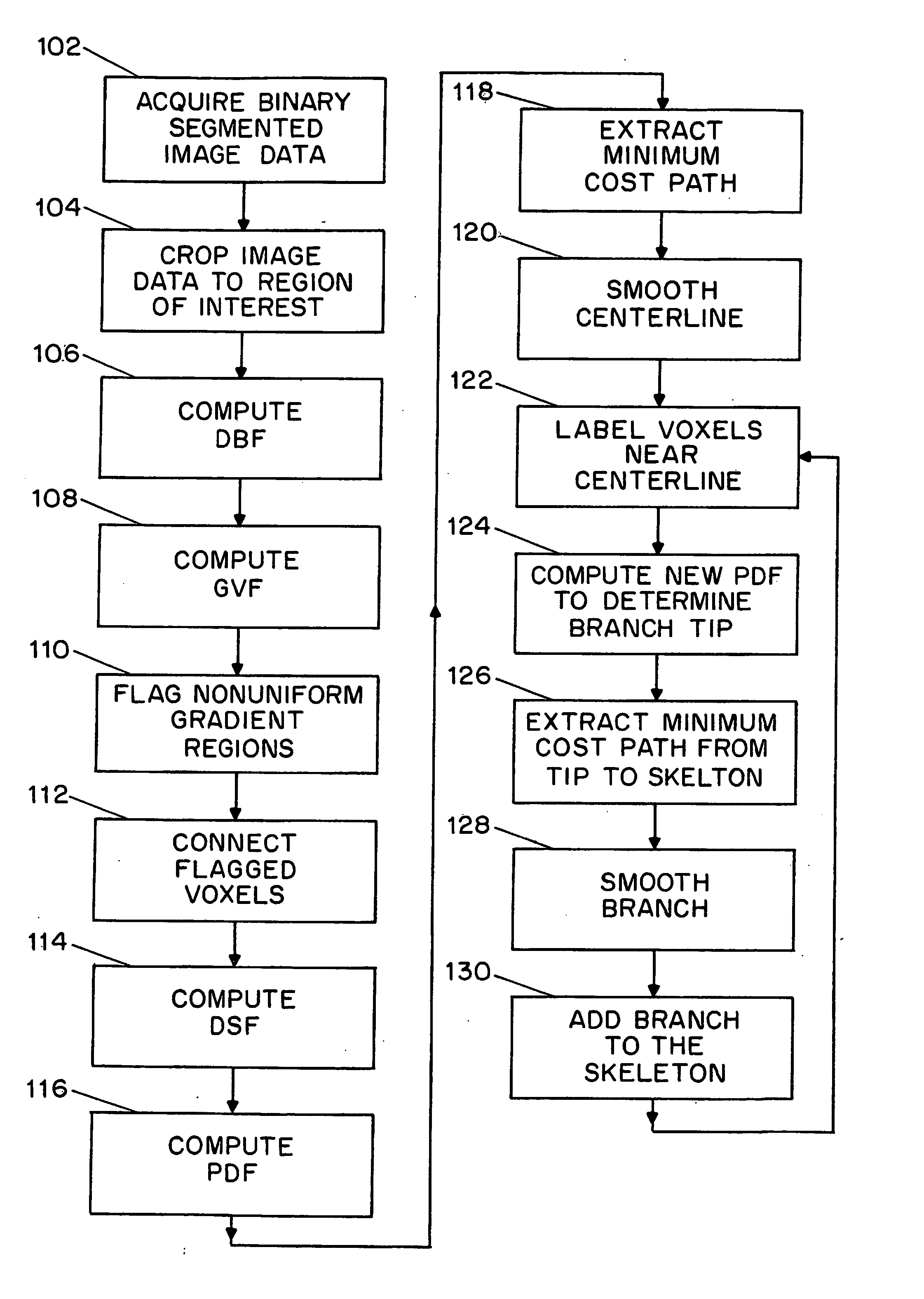
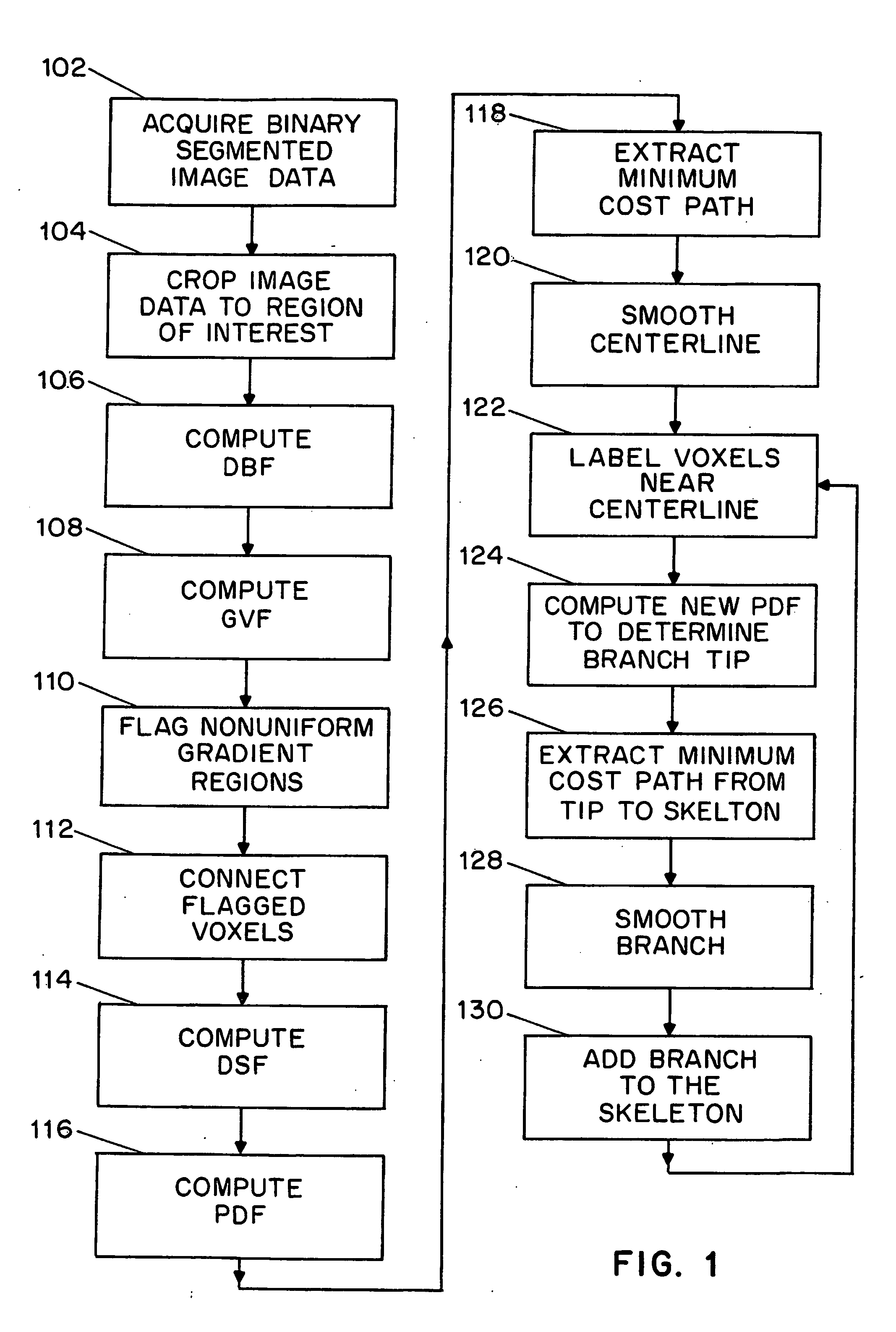
In accordance with the present invention, a method for determining a centerline through a region of interest in a 3D image dataset is provided. The method includes identifying the boundaries of the region of interest and identifying the endpoints of the region of interest. For those points within the boundaries, a penalty value which is a function of the proximity of the point to a boundary is determined. A centerline is then identified by the path connecting the endpoints which has the minimum penalized distance wherein the penalized distance reflects the actual accumulated pathlength and the penalties associated with the points along the path. From the centerline, branches of a complete skeleton can be established by determining branch endpoints and then finding the minimum penalized distance from each endpoint the centerline or another intersecting branch.

Description

FIELD OF THE INVENTION[0002] The present invention relates generally to computer-based three dimensional visualization and more particularly relates to improved methods for virtual navigation including skeleton generation.BACKGROUND OF THE INVENTION[0003] In many computer-based visualization systems, it is desirable to be able to define a skeleton or centerline through the object being viewed. Such a skeleton provides a reference path for virtual navigation, such as in virtual colonoscopy. Similarly, accurate length measurements and navigation through other organs, such as the aorta, also require an object skeleton. Of course, the need to define an accurate centerline or tree is not limited to medical imaging. Other fields, such as virtual engineering and architecture would also benefit from accurate methods of defining a skeleton in tree like objects or generating a centerline in linear objects in various visualization applications.[0004] Various techniques are known for generating...

Claims


Application Information

Patent Timeline
IPC IPC(8): A61B5/00G01R33/32A61B5/055A61B6/03A61B8/00G01R33/54G06K9/44G06T5/00G06T7/00G06T7/60G06T17/00G06T19/00
CPCG06T2200/04G06T7/64G06T2207/20044G06T2207/20132G06T2207/30028G06T2207/30061G06T2207/30172G06T2210/41G06T15/08G06T15/10G06T19/20G06T2219/028G06T2219/2012G06T7/12G06T7/62G06T2207/10072
Inventor BITTER, INGMARWAN, MINGKAUFMAN, ARIE E.DACHILLE, FRANKKREEGER, KEVINLIANG, ZHENGRONGWAX, MARK R.
Owner THE RES FOUND OF STATE UNIV OF NEW YORK
Learn More