
Light guide apparatus, a backlight apparatus and a liquid crystal display apparatus

a technology of liquid crystal display and light guide, which is applied in the direction of lighting and heating equipment, identification means, instruments, etc., can solve the problems of low efficiency of light source usage, large distribution of emitted light, and difficulty in obtaining light emitted with an angle spread less than 10 degrees fwhm

Inactive Publication Date: 2004-06-03
AU OPTRONICS CORP
View PDF2 Cites 31 Cited by
  • Summary
  • Abstract
  • Description
  • Claims
  • Application Information

AI Technical Summary

Benefits of technology

[0066] For example, the light power is largely attenuated when the light is reflected back to the light guide 3 by the reflector 5, and the light is deflected by the prism sheets 6 and 7. In this manner, the relatively large light power is lost before it reaches the LCD panel 10, so that a relatively large power source (i.e., a large capacity battery in the case of the notebook PCs) is required. Further, in the case of the TN (Twisted Nematic) mode LCD apparatus, when the user sees the light passing through the liquid crystal molecules along an oblique direction (for example, the direction of 45 degrees separated from the normal line of the display surface) the transmitted light power (i.e., the luminance) is decreased, so that the contrast ratio is decreased.

Problems solved by technology

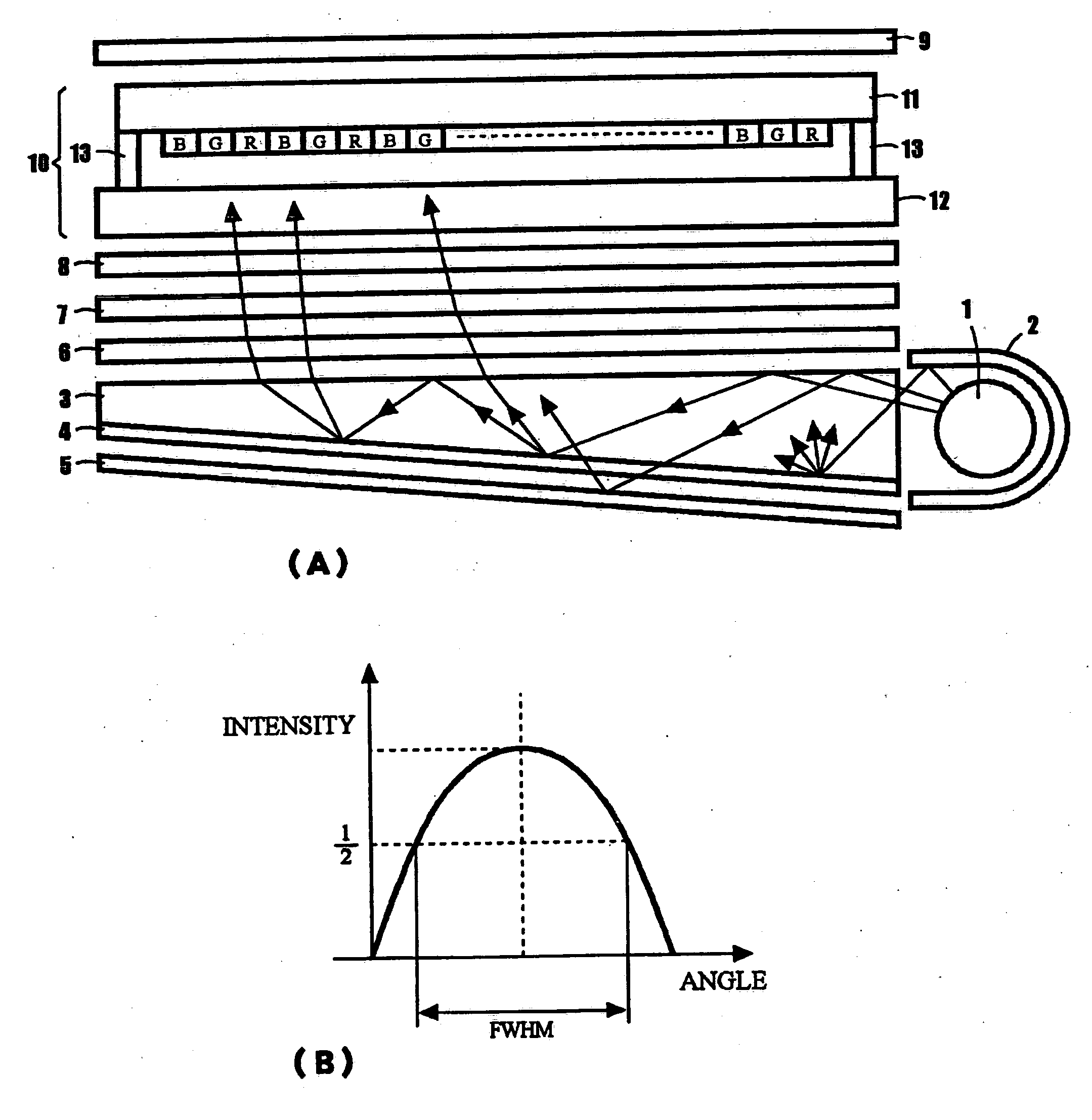
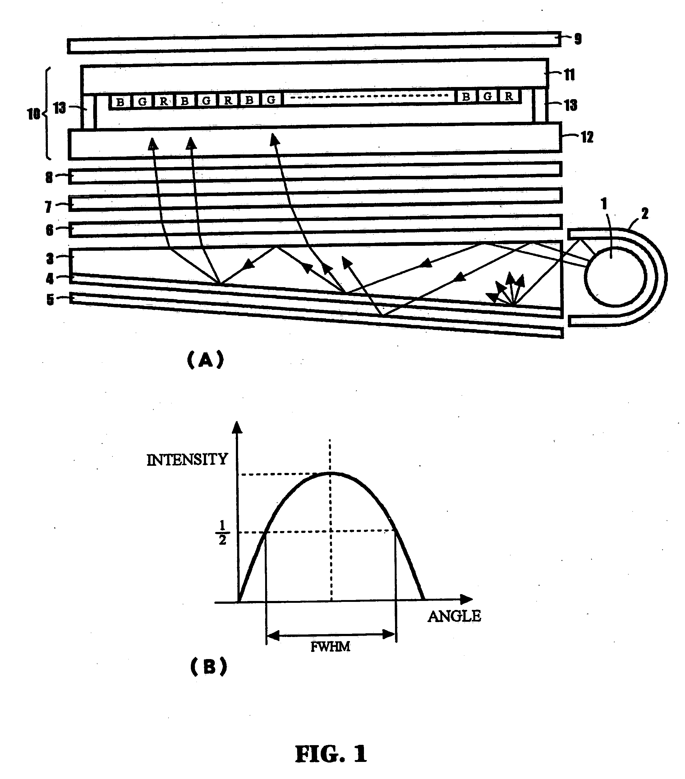
For some applications such as an LCD apparatus for notebook personal computers, this angle distribution of the emitted light is so large that the efficiency of usage of the light from the light source, or the fluorescent lamp 1 is not high.
A first problem of the conventional backlight apparatus is that it is very difficult to obtain the light emitted with an angle spread less than 10 degrees FWHM (Full Width at Half Maximum), as shown in FIG. 1(B).
Another problem of the conventional backlight apparatus is that the backlight apparatus requires many components, some of which are not easily fabricated, so that the fabrication cost becomes high.
A third problem of the conventional backlight apparatus is that since the light from the fluoresecent lamp 1 passes through many components, the intensity of the light is largely attenuated while passing through the components.

Method used


Image

  • Light guide apparatus, a backlight apparatus and a liquid crystal display apparatus
  • Light guide apparatus, a backlight apparatus and a liquid crystal display apparatus
  • Light guide apparatus, a backlight apparatus and a liquid crystal display apparatus

Examples


first embodiment

[0049] First Embodiment

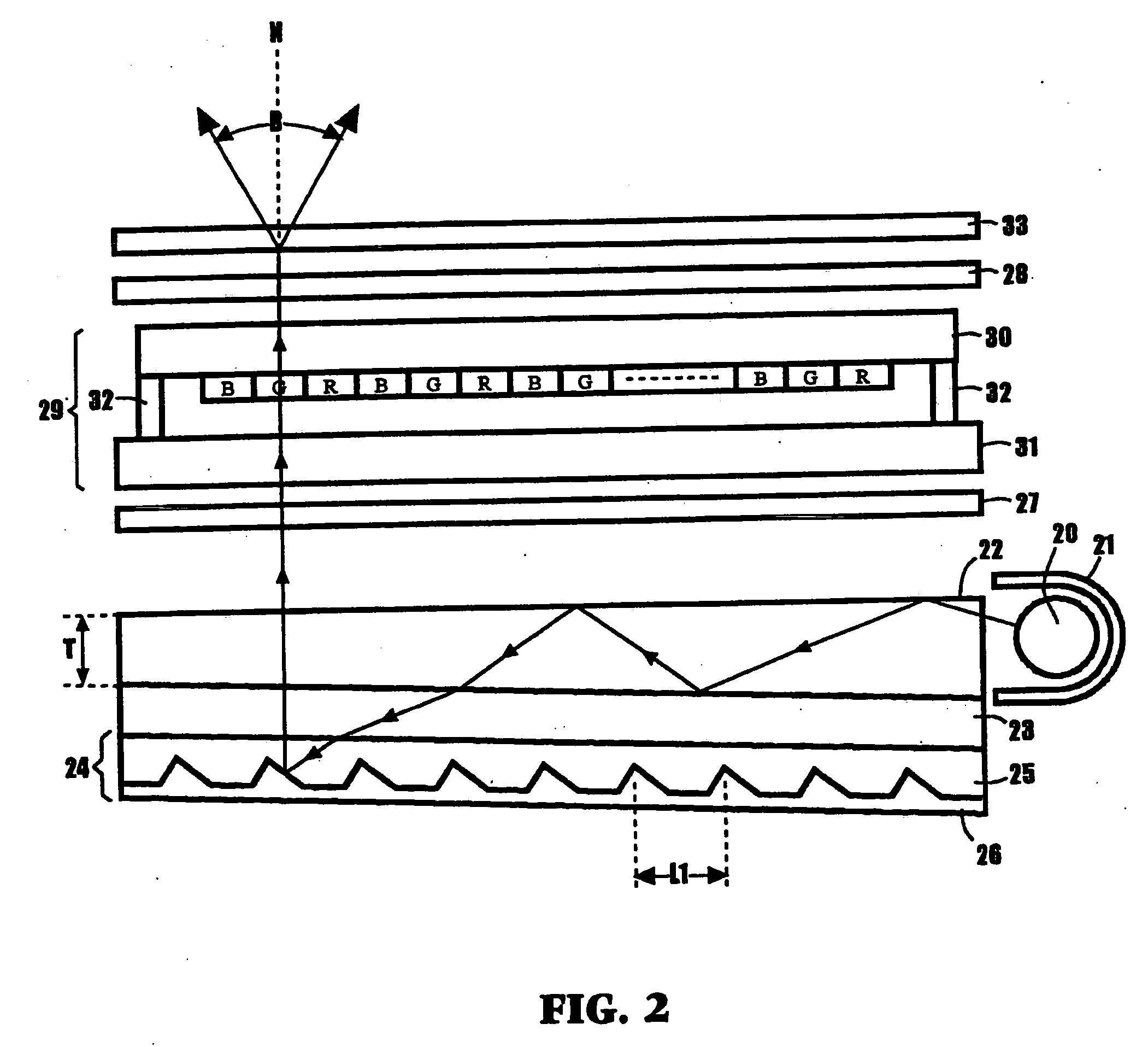
[0050] FIG. 2 shows a first embodiment of the color LCD apparatus using the backlight apparatus in accordance with the present invention. The backlight apparatus includes a light source 20, such as a cold cathode fluorescent lamp, for generating white light, a reflecting cover 21 mounted to surround a top side, a bottom side and a rear side of the fluorescent lamp 20, a wedge-type light guide 22 of a refractive index n1, a first light transmission layer 23 of a refractive index n2, which is smaller than the refractive index n1 of the light guide 22 and is larger than the refractive index of the air, which is about 1.0, and a light deflecting layer 24 of the refractive index substantially equal to the refractive index n1 of the light guide 22.

[0051] The top surface and the bottom surface of the first light transmission layer 23 are parallel to each other, and the top surface of the first light transmission layer 23 contacts the bottom surface of the wedge-type ...

second embodiment

[0082] Second Embodiment

[0083] FIG. 8 shows a second embodiment of the color LCD apparatus using the backlight apparatus in accordance with the present invention. The structure and the operation of the LCD apparatus of the second embodiment is similar to the LCD apparatus of the first embodiment shown in FIG. 2 except for the following differences: (1) the light deflecting layer 24 including a reflective diffraction grating 41 (FIG. 9) is used in the second embodiment, (2) the color filter is not formed in the LCD panel 29 in the second embodiment, (3) a cylindrical lens array 38 is provided between the polarizer 27 and the backlight apparatus in the second embodiment, and (4) an optical filter 39 is provided between the light source or the fluorescent lamp 20 and the light guide 22 to filter the light of the particular wavelength.

[0084] Regarding the light deflecting layer 24, FIG. 9 shows one of the light paths for a color separation by the reflective diffraction grating 41 in the...


PUM

PropertyMeasurementUnit
refractive index n2aaaaaaaaaa

Abstract

A backlight apparatus (and light guide and liquid crystal display apparatus incorporating the same) includes a wedge-type light guide having a refractive index n1, and having a top surface, a bottom surface and a side surface, a light source for directing light to the side surface of the wedge-type light guide, a first light transmission layer having a refractive index n2, which is smaller than said refractive index n1, and having a top surface and a bottom surface, wherein the top surface of the first light transmission layer is attached to the bottom surface of the wedge-type light guide, and a light deflecting layer having a top surface attached to the bottom surface of the first light transmission layer for deflecting the incident light from the first light transmission layer toward the top surface of the wedge-type light guide.

Description

[0001] 1. Field of the Invention[0002] The present invention relates to a light guide apparatus, a backlight apparatus and a liquid crystal display (LCD) apparatus using the backlight apparatus.[0003] 2. Description of the Related Art[0004] A backlight apparatus has been used as a light source of an LCD apparatus. FIG. 1(A) shows an LCD apparatus using a conventional backlight apparatus. The conventional backlight apparatus includes a fluorescent lamp 1 generating white light, a reflecting cover 2 mounted to surround a top side, a bottom side and a rear side of the fluorescent lamp 1, a wedge-type light guide 3, a light scattering layer 4 attached on the bottom surface of the light guide 3, a metallic reflector 5 placed below the light guide 3, and light-shaping films 6 and 7 placed above the light guide 3. A prism sheet, which refracts the incidence light directed from an oblique direction toward a vertical direction of the prism sheet, is frequently used as the light-shaping films...

Claims


Application Information

Patent Timeline
Patent Type & Authority Applications(United States)
IPC IPC(8): G09F9/00F21V8/00F21Y103/00G02B6/00G02F1/13G02F1/1335G02F1/13357
CPCG02B6/0046G02F1/133615G02B6/0053G02F1/1335
Inventor TAIRA, YOICHIYAMADA, FUMIAKINISHIKAI, AKIKO
Owner AU OPTRONICS CORP
Learn More