
Electro-absorption modulated laser using coupling for chirp correction

a chirp correction and chirp correction technology, applied in semiconductor lasers, laser details, electrical devices, etc., can solve the problems of large dispersion penalty, large dp, and low transmission performance of known emls, so as to reduce bias voltage, reduce aop, and increase absorption

Inactive Publication Date: 2007-10-11
CYOPTICS ISRAEL
View PDF1 Cites 14 Cited by
  • Summary
  • Abstract
  • Description
  • Claims
  • Application Information

AI Technical Summary

Benefits of technology

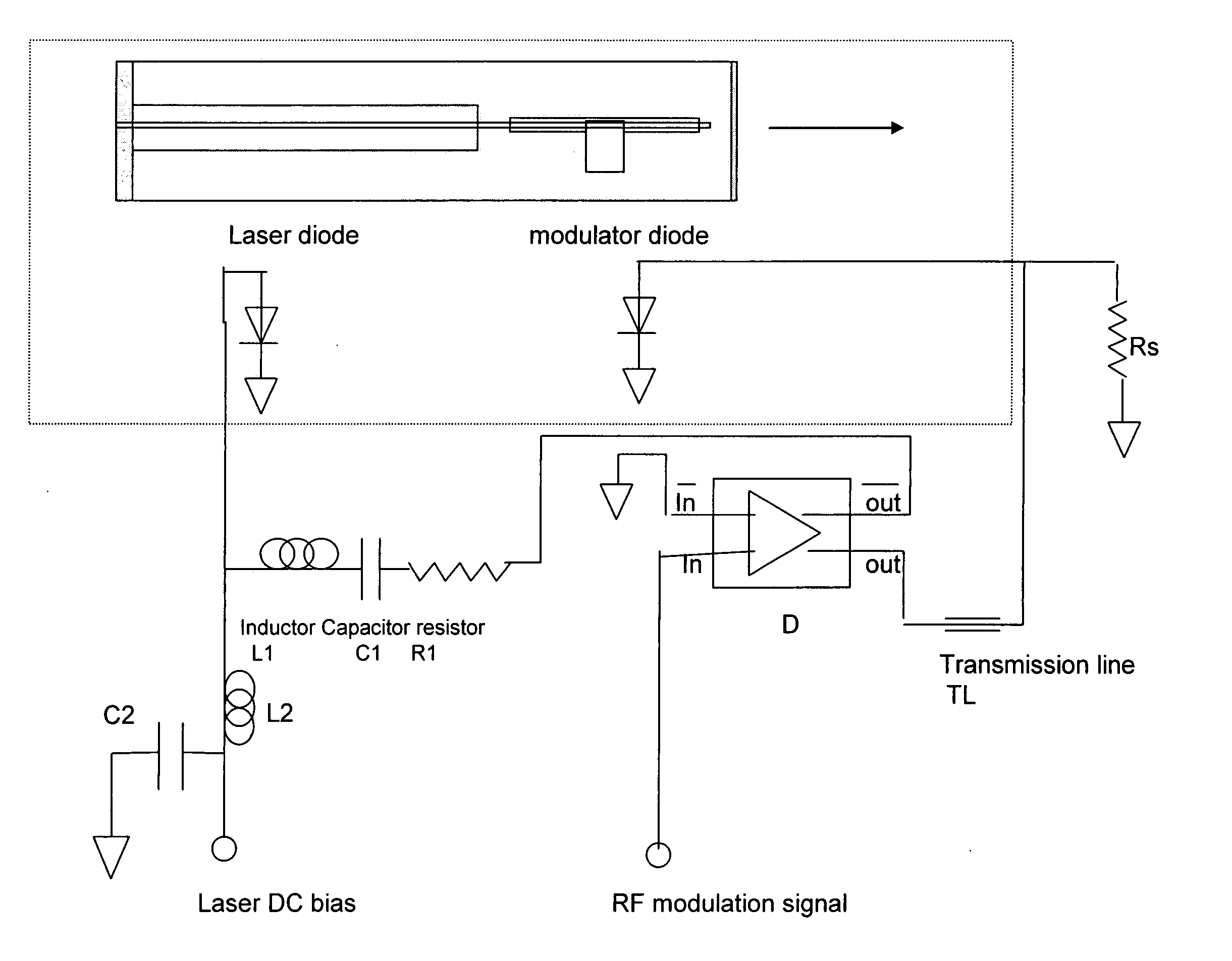
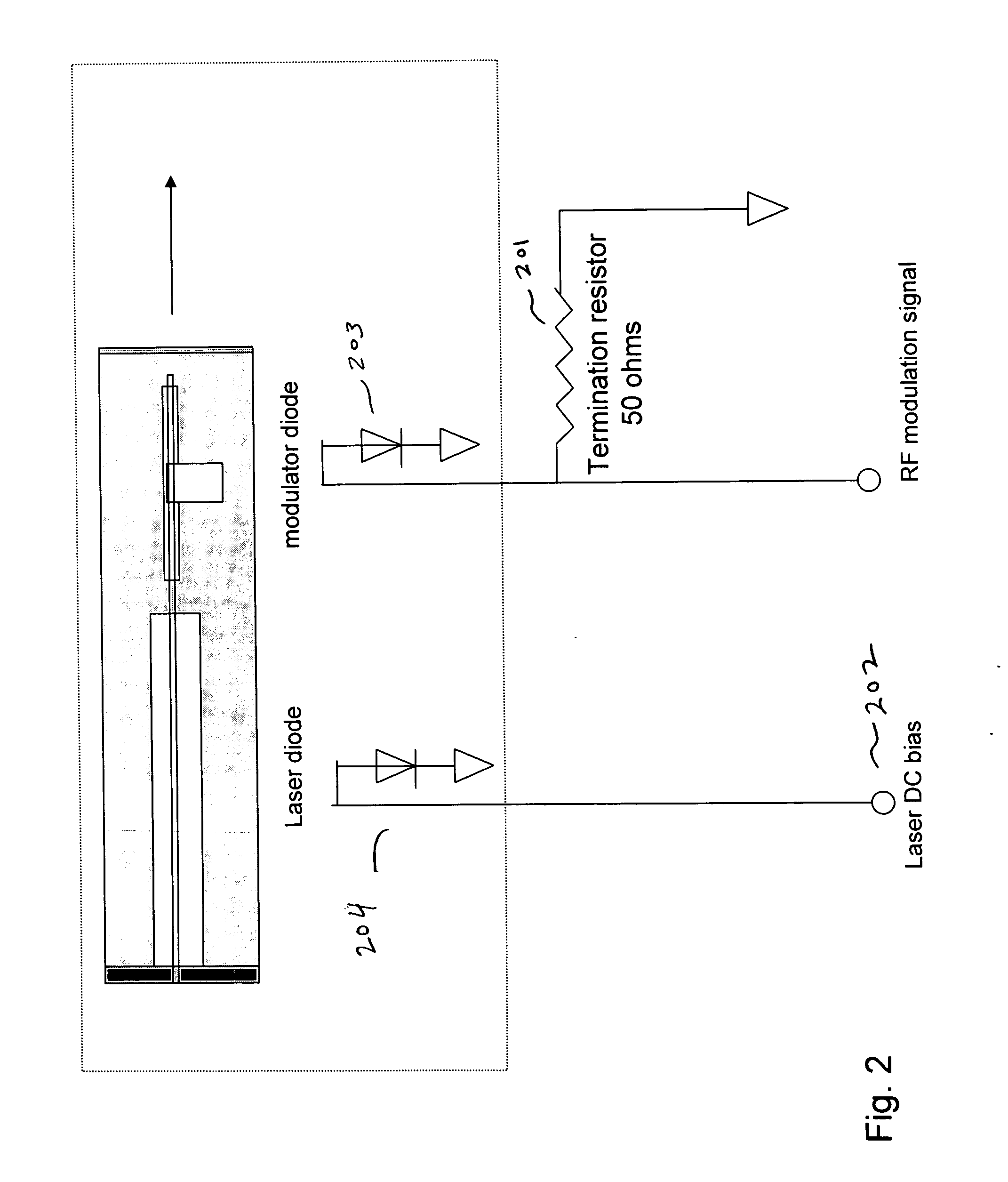
[0002] The chirp of an electroabsorption (EA) modulator depends on its bias work point. Lowering the bias voltage on the EA modulator causes the chirp to become negative. However, by lowering the bias voltage on the modulator the average optical power (AOP) emitted from the device also decreases due to the larger absorption of the modulator at the work point.

Problems solved by technology

The distance of transmission is often limited by dispersion of light in the fiber which is causing a large dispersion penalty (DP) as transmission distance is increased.
However, by lowering the bias voltage on the modulator the average optical power (AOP) emitted from the device also decreases due to the larger absorption of the modulator at the work point.
Unfortunately, known EMLs are often limited in transmission performance.

Method used


Image

  • Electro-absorption modulated laser using coupling for chirp correction
  • Electro-absorption modulated laser using coupling for chirp correction
  • Electro-absorption modulated laser using coupling for chirp correction

Examples


Embodiment Construction

[0018] In the following detailed description, for purposes of explanation and not limitation, example embodiments disclosing specific details are set forth in order to provide a thorough understanding of an embodiment according to the present teachings. However, it will be apparent to one having ordinary skill in the art having had the benefit of the present disclosure that other embodiments according to the present teachings that depart from the specific details disclosed herein remain within the scope of the appended claims. Moreover, descriptions of well-known apparati and methods may be omitted so as to not obscure the description of the example embodiments. Such methods and apparati are clearly within the scope of the present teachings.

[0019] In accordance with the first example embodiment described herein, the laser frequency is changed to improve the transmission performance by adding a current signal to the laser that follows the modulator signal with a small time delay. In...


PUM


Abstract

An electroabsorption modulated laser (EML) which uses coupling for chirp correction is disclosed.

Description

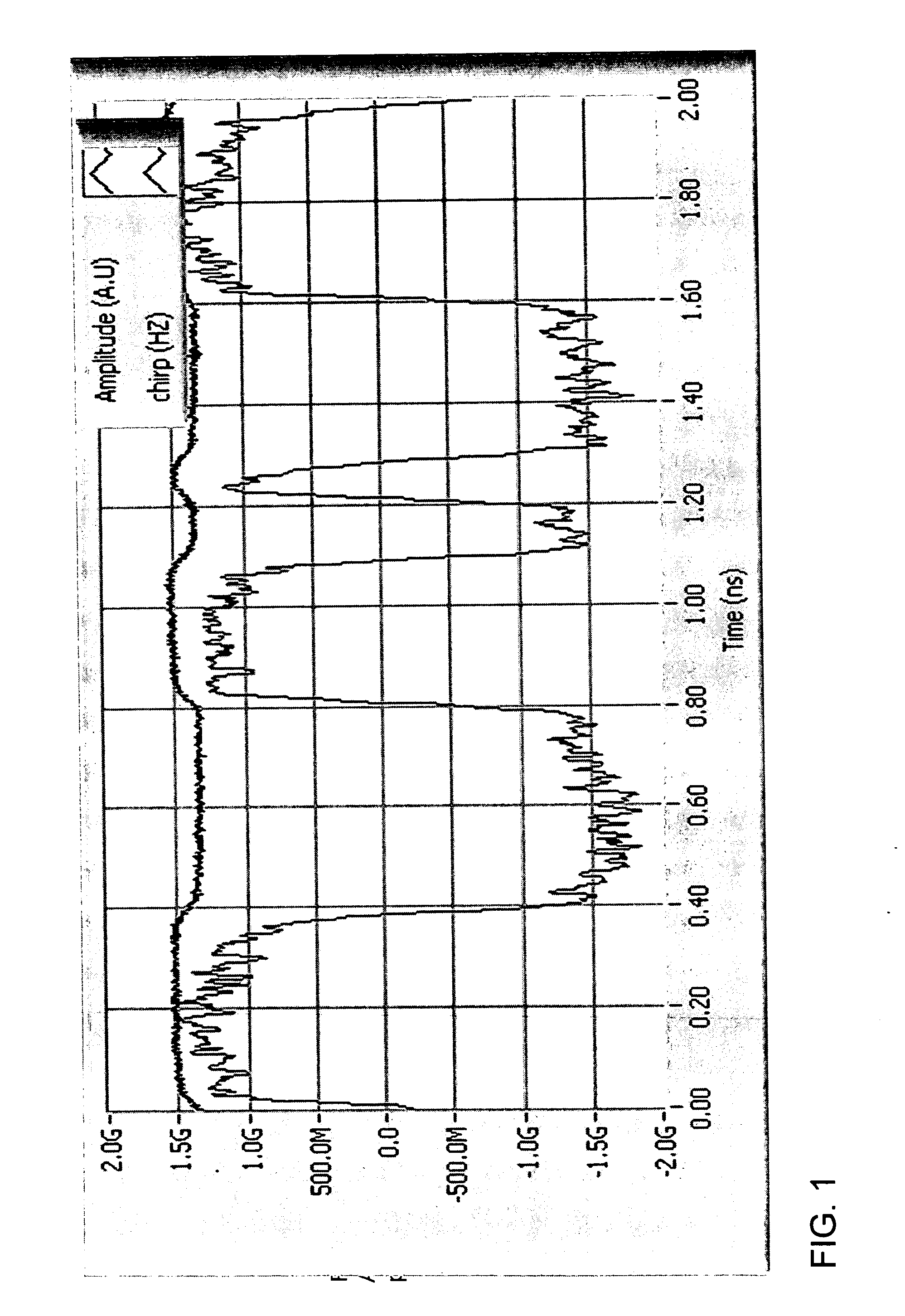
BACKGROUND AND SUMMARY [0001] Integrated electroabsorption modulated lasers (EML's) are laser and electroabsorption modulator integrated on the same chip. These devices are used in the transmission of digital optical signals through long spans of optical fibers at high bit rates. The distance of transmission is often limited by dispersion of light in the fiber which is causing a large dispersion penalty (DP) as transmission distance is increased. The DP depends on the dynamic wavelength excursions (referred to as ‘dynamic chirp’) associated with amplitude modulation of the optical signal. The dynamic chirp is caused by the modulator during rise and fall times of the digital signal. In order to improve the transmission it is useful to control the chirp that is generated by the EML. For example, it is well known that in normal dispersion fiber negative chirp is required to increase transmission distance beyond about 60 km at 10 Gb / sec bit rates. [0002] The chirp of an electroabsorptio...

Claims


Application Information

Patent Timeline
Patent Type & Authority Applications(United States)
IPC IPC(8): H01S3/10H01S3/13
CPCH01S5/0265H01S5/0622H01S5/06213H01S5/0427
Inventor FINZI, DAVIDKOREN, UZIEL
Owner CYOPTICS ISRAEL
Learn More