Method for determining charging capacitance of capacitor

a capacitor and capacitance measurement technology, applied in the direction of electric fuzes, lighting and heating apparatus, instruments, etc., can solve the problems of increasing the number of connectors, increasing the weight of these connectors, and increasing the volume of the connectors

Active Publication Date: 2004-05-20
DAICEL CHEM IND LTD
View PDF19 Cites 8 Cited by
  • Summary
  • Abstract
  • Description
  • Claims
  • Application Information

AI Technical Summary

Problems solved by technology

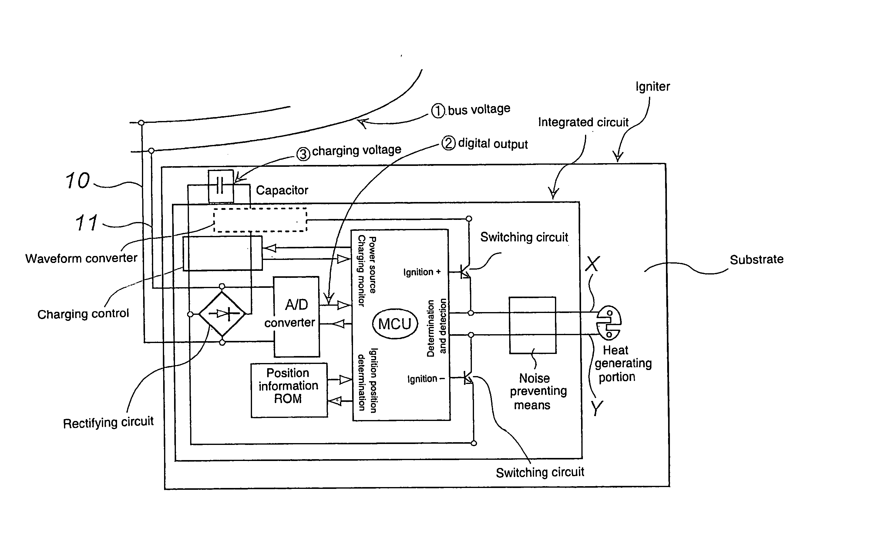
In view of constraints at a time of assembling vehicle parts, the ECU and the individual gas generators are connected not only by the conductors but by connecting plural conductors via plural connectors, and thereby, there occurs a serious problem such as a weight increase due to these connectors and a cost increase due to increase of the number of the connectors.
Further, increase in weight due to increase in volume of the capacitor assembled in the ECU as a backup power source (in case of disconnection between the power source and the ECU) for activating all of the igniters cannot be ignored.
In the air bag system shown in FIG. 1, however, as the resistance value of the heat generating portion of the igniter has been made small, influence of resistance values of other elements can not be ignored.
Furthermore, although such an extra charging voltage or charging capacitance is expected, the resistance value of elements other than the heat generating portion or the like is not accounted, so that, when an amount of power consumed at these portions is large, the heat generating portion does not generate heat sufficiently.
When the switching circuit is OFF, electricity stored in the capacitor does not flow in the heat generating portion, but the integrated circuit consumes a certain amount of power to recognize an actuation signal or the like.
There is a drawback such that, when the charging voltage is high, a capacitor with a high voltage proof is required and that a capacitor capacitance storing necessary energy therein must be made large when the charging voltage is too low.
For example, when there i...

Method used


Image

  • Method for determining charging capacitance of capacitor
  • Method for determining charging capacitance of capacitor
  • Method for determining charging capacitance of capacitor

Examples


first embodiment

[0077] (1) First Embodiment

[0078] First, an air bag system in which a method of determining a charging capacitance of a capacitor of the invention described in claim 1 is employed will be explained with reference to FIG. 1 to FIG. 7.

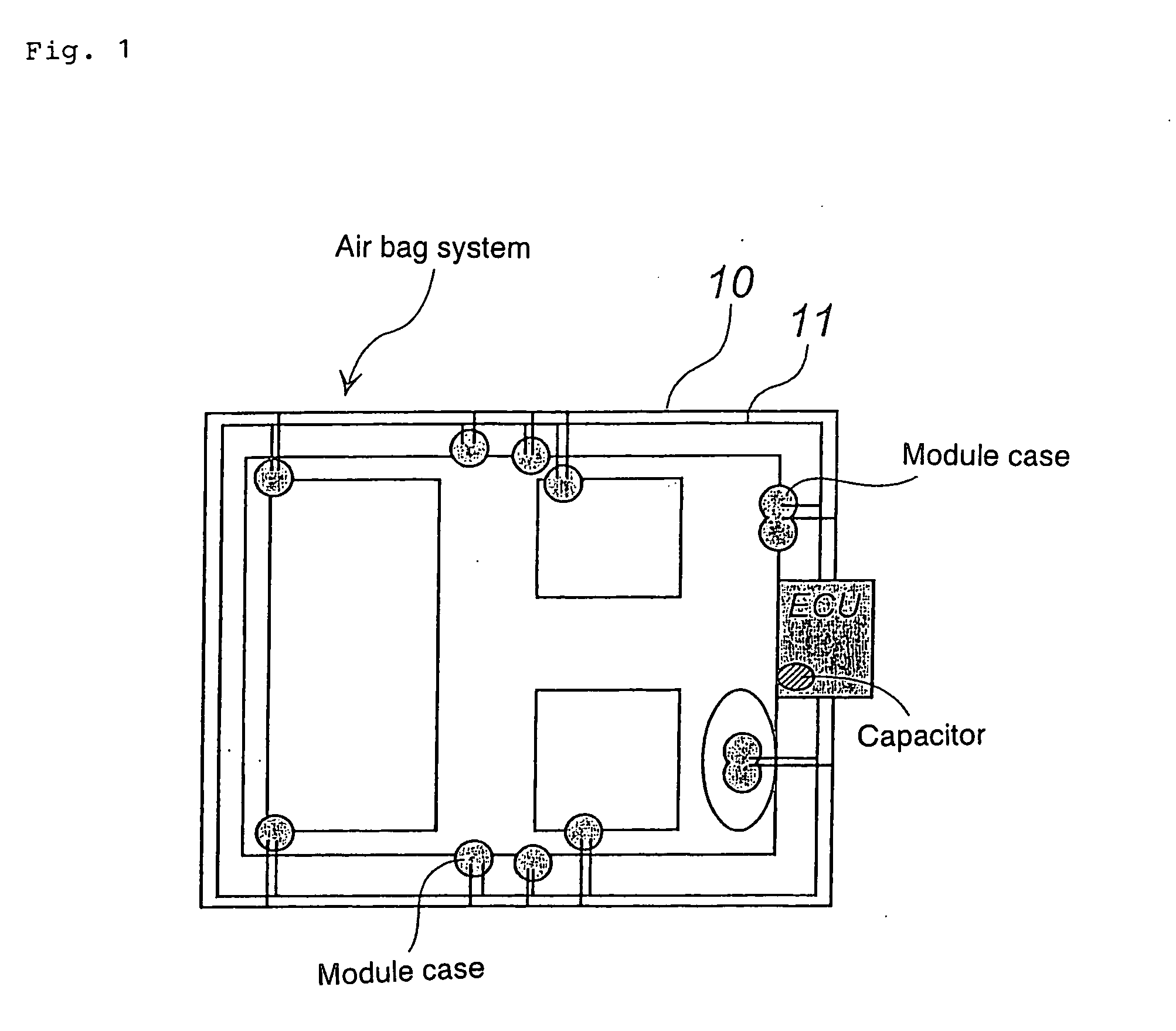
[0079] As shown in FIG. 1, an air bag system employing a bus system uses bus lines 10 and 11 comprising two loop wires passing through an ECU. The ECU is connected to a power source (a battery in a vehicle) and an impact detecting sensor which are not illustrated, and a capacitor for backup, when a conductor (a lead wire) connecting the ECU and the power source is disconnected by an impact at a collision of a vehicle, is disposed. Incidentally, in the air bag system shown in FIG. 1, since the capacitor is disposed at each gas generator (igniter), the capacitor for backup may have a small capacitance (i.e., light weight), but the capacitor for backup in the conventional air bag system shown in FIG. 8 has to have a large capacitance in order to activate al...

second embodiment

[0126] (2) Second Embodiment

[0127] An air bag system of the invention described in claim 3 will be explained with reference to FIGS. 1 to 3, FIG. 9 and FIG. 10 to FIG. 12.

[0128] As shown in FIG. 1, an air bag system employing the bus system uses bus lines 10 and 11 comprising two loop wires passing through an ECU. The ECU is connected to a power source (a battery in a vehicle) and an impact detecting sensor which are not illustrated, and a capacitor for backup, when a conductor (a lead wire) connecting the ECU and the power source is disconnected by an impact at a collision of a vehicle, is further disposed. Incidentally, in the air bag system shown in FIG. 1, since the capacitor is disposed between each gas generator (igniter) and the bus lines (desirably, in the connector connecting to the igniter), the capacitor for backup may have a small capacitance (i.e., light weight), but the capacitor for backup in the conventional air bag system shown in FIG. 8 has to have a large capacita...


PUM


Abstract

The present invention provides a method of determining a charging capacitance of a capacitor in an air bag system using a bus system. The method is a method of determining a charging capacitance of a capacitor in which a charging capacitance of a capacitor required for activating an air bag system normally is obtained from the following formula (I). C=l 2E/V<2> (I) (In the formula, C represents a capacitor charging capacitance, V represents a charging voltage, and E represents the minimum ignition energy required for making the heat generating portion of the igniter generate heat to ignite a priming, which is obtained by the following formula (II): E=Imin<2>x(Rmax+r1+r2)xT+wxl 10 (II) Imin: the minimum ignition current value (A) Rmax the maximum resistance value of the heat generating portion (Omega) r1: an ON resistance value of the switching circuit (the maximum ON resistance value at 150° C.) (Omega) r2: a resistance value of the other elements (Omega) T: a time period in which a current flows in the heat generating portion (sec) w: a power consumed by the whole integrated circuit when the switching circuit is OFF)

Description

TECHNICAL FIELD TO WHICH THE INVENTION BELONGS[0001] The present invention relates to a method of determining an optimal capacitance of a capacitor used in an air bag system utilizing a bus line, and an air bag system utilizing a bus line.PRIOR ART[0002] An air bag system for protecting a passenger from an impact at a time of collision of a vehicle is indispensable, and air bag system needs to be reduced in weight from a demand of reducing weight of a whole vehicle. Recently, kinds and the total number of air bags such as an air bag for a driver side, an air bag for a passenger side next to the driver, an air bag for a rear seat, and an air bag for an side collision are increasing, and therefore, a lighter air bag system is in greater demand.[0003] In a current air bag system, an electronic control unit (ECU) connected to a power source (a battery in a vehicle) and an impact detecting sensor is individually connected to respective gas generators (a gas generator and an air bag are a...

Claims


Application Information

Patent Timeline
IPC IPC(8): B60R21/01F42B3/04F42B3/12G01R31/01
CPCB60R21/017B60R2021/01054G01R31/028F42B3/121F42B3/04G01R31/64
Inventor OKAMOTO, MITSUYASUODA, SHINGO
Owner DAICEL CHEM IND LTD
Why Eureka
Try Eureka