
Arrangement of a data coupler for power line communications

a data coupler and power line technology, applied in the field of power line communication, can solve the problems of excessive coupling attenuation between the power line and the communication device, low magnetization inductance, and relatively long capacitor to the power lin

Inactive Publication Date: 2004-05-13
ERICSSON INC
View PDF4 Cites 26 Cited by
  • Summary
  • Abstract
  • Description
  • Claims
  • Application Information

AI Technical Summary

Benefits of technology

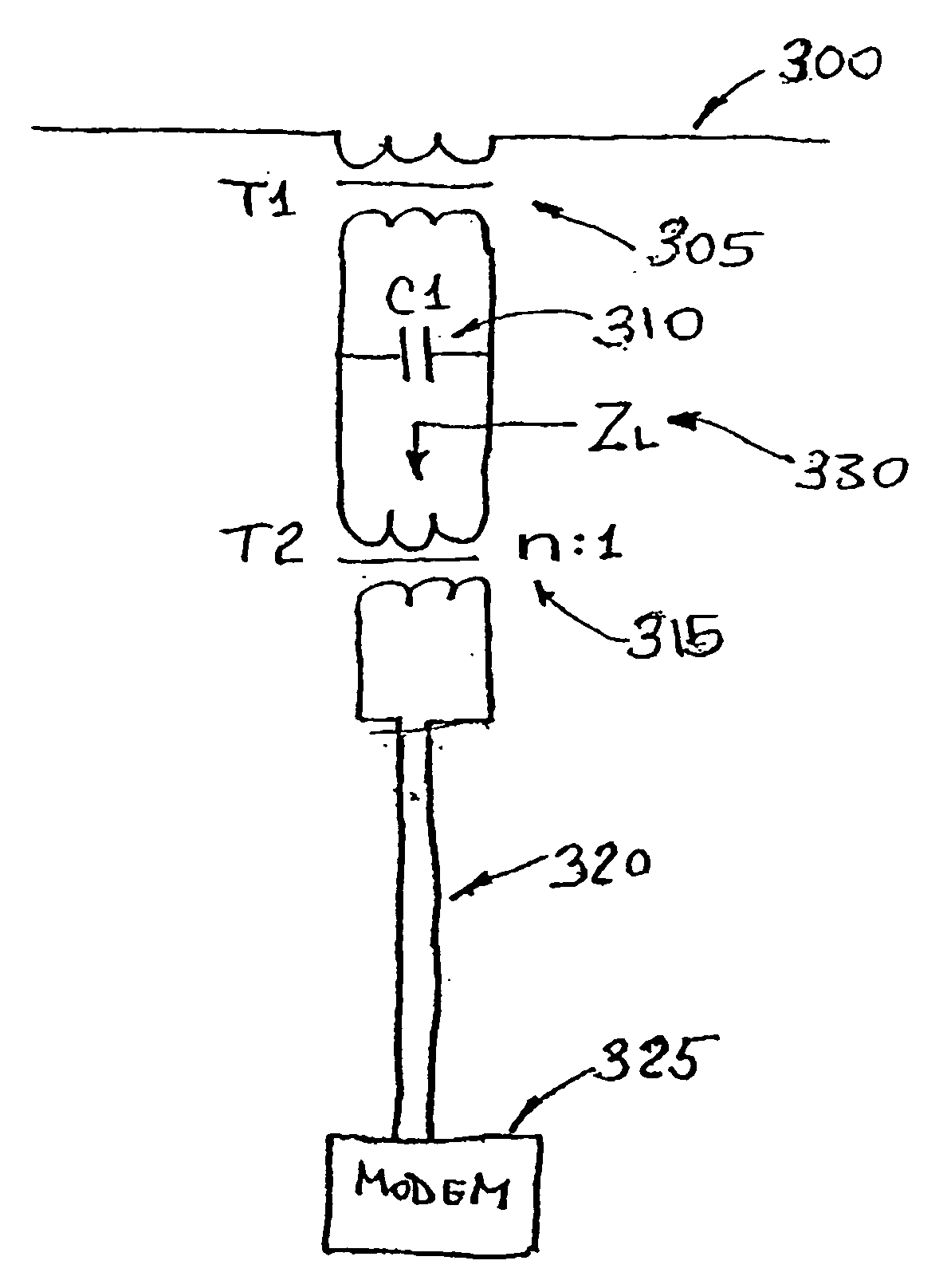
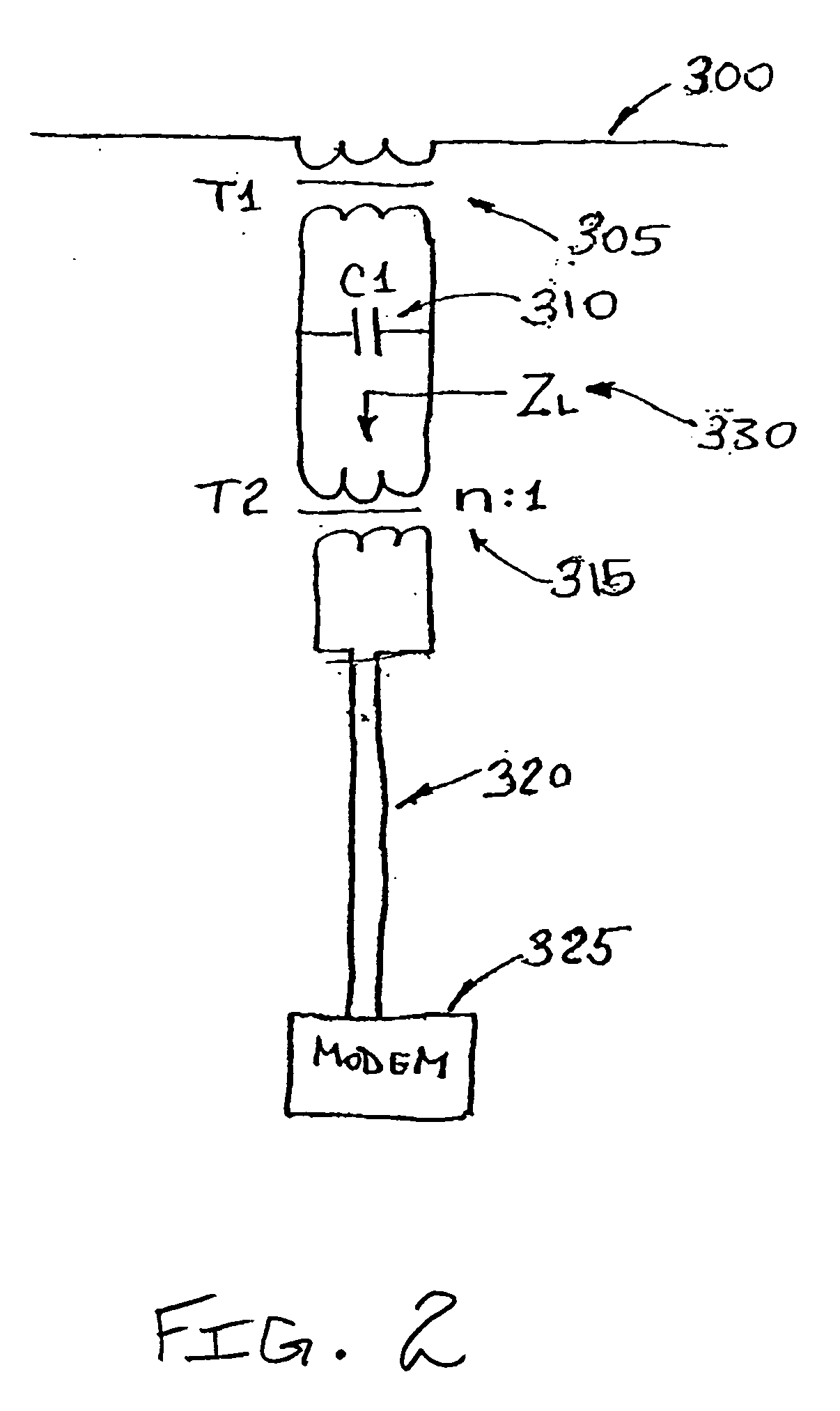
"The present invention relates to power line communications and more particularly to data couplers for power line communications. The invention aims to improve the performance of data couplers by reducing the cutoff frequency and impedance at signal frequencies. The invention proposes a low frequency inductive coupler that extends the cutoff frequency downwards, reducing the inductance of the coupler. The coupler is clamped around the power line conductor, which serves as the primary winding for the inductive coupler. A shunt capacitor may be added to neutralize the magnetization inductance. An impedance matching transformer is connected between the coupler and the modem to adjust the modem's impedance and provide a low enough loaded Q to increase bandwidth. The invention also provides a circuit for connecting a modem to an inductive coupler using a shunt capacitor and an impedance matching transformer. The invention improves the performance of data couplers for power line communications."

Problems solved by technology

Below the cutoff frequency, coupling attenuation between the power line and the communication device becomes excessive.
As the magnetization inductance is in shunt with a signal and inductively loads the signal, a low magnetization inductance is undesirable.
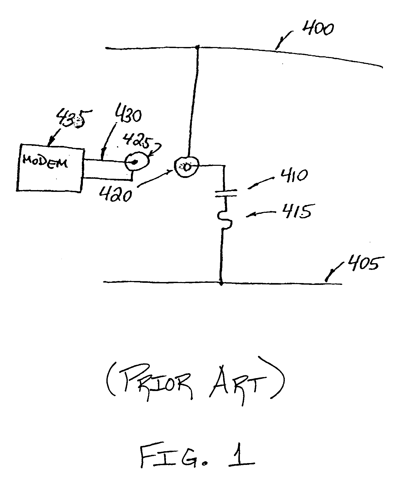
However, a lead connecting such a capacitor to the power line may be relatively long, and may have an impedance far exceeding the capacitor's impedance at signal frequencies.

Method used


Image

  • Arrangement of a data coupler for power line communications
  • Arrangement of a data coupler for power line communications
  • Arrangement of a data coupler for power line communications

Examples


Embodiment Construction

[0018] A low frequency inductive coupler in accordance with the present invention extends cutoff frequency downwards, to a lower frequency, without resorting to an addition of heavy magnetic cores. The inductive coupler is clamped around an energized power line conductor of the power line. Assume that the power line conductor passing through a core of the coupler serves as a primary winding for the inductive coupler. Since the coupler is clamped around the power line conductor, and since the power line conductor serves as a primary winding, the coupler has only a one-turn primary winding. The physical dimensions of the power line conductor typically require that the core be large with a long magnetic circuit path. An air gap may be required to prevent saturation of the core. Both of these factors reduce the inductance of the coupler.

[0019] A classic method of reducing reactive loading in a circuit is to resonate an offending reactance with an opposite reactance. In the case of an in...


PUM

PropertyMeasurementUnit
inductanceaaaaaaaaaa
lengthaaaaaaaaaa
impedanceaaaaaaaaaa

Abstract

There is provided an arrangement of components for coupling data between a power line and a communication device. The arrangement includes an inductive coupler that employs a power line conductor as a primary winding, a capacitor connected across a secondary winding of the inductive coupler for creating a resonant circuit with the secondary winding at a frequency within a desired frequency band, and an impedance matching transformer for connecting a communications device to the secondary winding. The resonant circuit has a loaded Q consistent with the desired bandwidth. An alternative arrangement includes a capacitor in series with a conductive cylinder between the power line and the communication device, where the capacitor is for blocking power line voltage while passing a signal between the power line and the communication device, and the conductive cylinder appears as a low inductance to the signal.

Description

[0001] The present application is claiming priority of U.S. Provisional Patent Application Serial No. 60 / 419,174, filed on Oct. 17, 2002, the content of which is herein incorporated by reference.[0002] 1. Field of the Invention[0003] The present invention relates to power line communications, and more particularly, to configurations of data couplers for power line communications.[0004] 2. Description of the Related Art[0005] A data coupler for power line communications couples a data signal between the power line and a communication device such as a modem. The data coupler exhibits a cutoff frequency. Below the cutoff frequency, coupling attenuation between the power line and the communication device becomes excessive. The data coupler may be either an inductive coupler or a capacitive coupler.[0006] An inductive coupler for a power line should ideally have a magnetization inductance with an impedance that is large as compared to an impedance of the communication device. As the magn...

Claims


Application Information

Patent Timeline
Patent Type & Authority Applications(United States)
IPC IPC(8): H01F17/06H01F38/14H01F38/20H01P1/32H03H1/00H03H5/00H03H7/01H03H7/09H03H7/38H04B3/36H04B3/38H04B3/54H04B3/56H04M11/04
CPCH01F17/06H04B2203/5491H03H7/0115H03H7/0138H03H7/38H03H2001/0092H03H2007/013H04B3/38H04B3/54H04B3/542H04B3/56H04B2203/5408H04B2203/5425H04B2203/5479H04B2203/5483H01F2038/143H01F38/02H01P1/32H04M11/04
Inventor CERN, YEHUDA
Owner ERICSSON INC
Learn More