Apparatus and methods of detection of radiation injury using optical spectroscopy

a radiation injury and optical spectroscopy technology, applied in the field of apparatus and methods of radiation injury detection using optical spectroscopy, can solve the problems of unable to differentiate between limited tissue specificity of ionizing radiation, and damage to both normal and neoplastic brain tissues

Inactive Publication Date: 2004-04-22
VANDERBILT UNIV
View PDF60 Cites 20 Cited by
  • Summary
  • Abstract
  • Description
  • Claims
  • Application Information

AI Technical Summary

Problems solved by technology

Unfortunately, ionizing radiation has limited tissue specificity and damages both normal and neoplastic brain tissues.
Unfortunately, with CT and MRI, it is often impossible to differentiate these two entities.
However, even stereotactic biopsy of enhancing lesions identified on MRI may be inaccurate due to sampling error.
As any viable tumor cells may lead to treatment failure and death, the discovery of viable tumor cells may radically alter clinical decision-making.
However, relatively few studies have addressed the diagnostic potential of optical spectroscopy in brain tumors.
Particularly, fluorescence characteristics of radiation-injured brain tissues have not yet been developed.

Method used


Image

  • Apparatus and methods of detection of radiation injury using optical spectroscopy
  • Apparatus and methods of detection of radiation injury using optical spectroscopy
  • Apparatus and methods of detection of radiation injury using optical spectroscopy

Examples


Embodiment Construction

APPARATUS SETUP AND MEASUREMENT

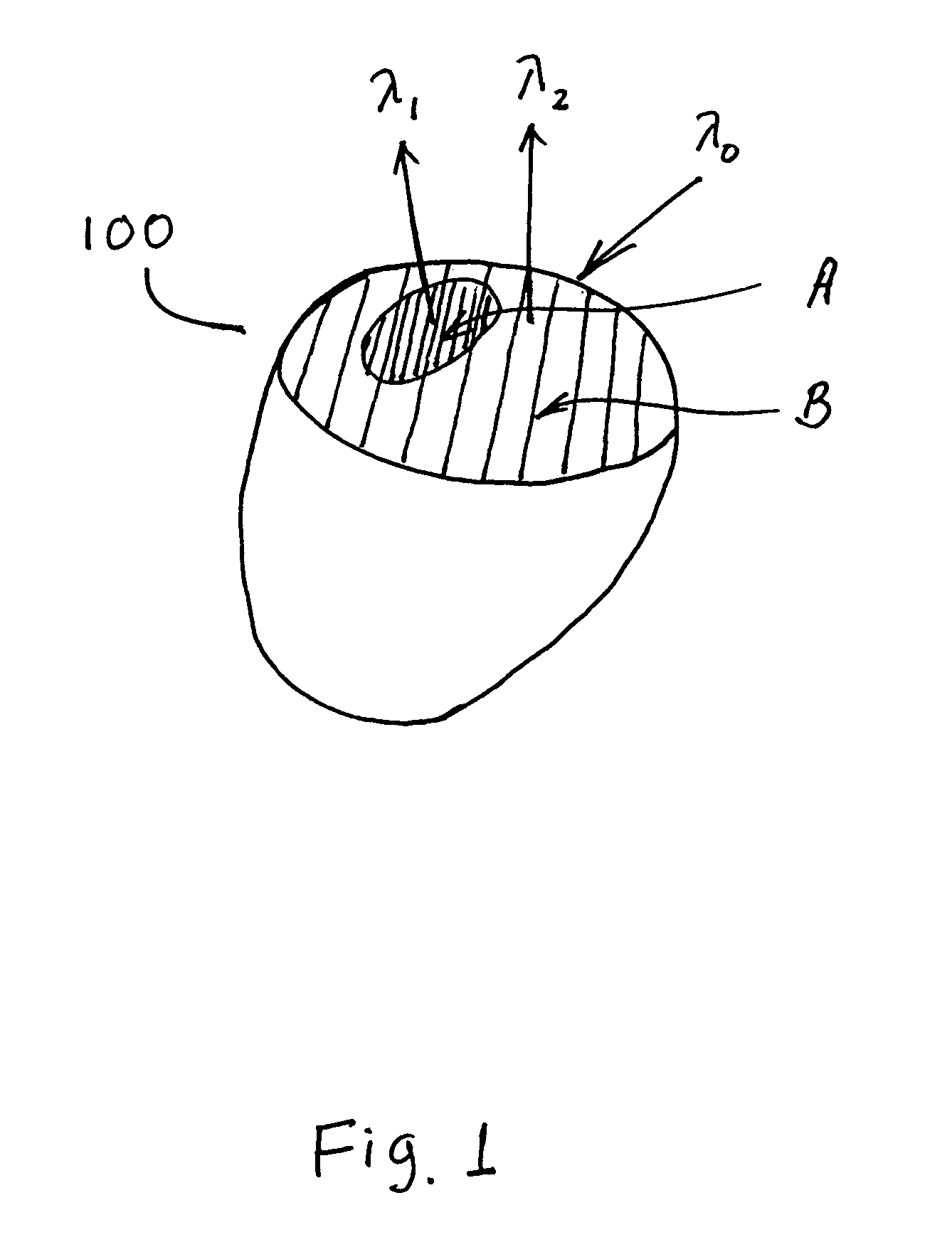
[0048] Referring now to FIG. 3, in one embodiment of the present invention, an apparatus 300 includes a source of laser light 330, a fiber optical probe 340 coupled with the source of laser light 330 so as to deliver the laser light to a working end 342 of the fiber optical probe 340, and a spectrograph or spectroscope 360 coupled with the fiber optical probe 340 so as to receive fluorescent light emitted from in vivo brain tissues 100 contacted by the working end 342 of the fiber optical probe 340 and providing a frequency spectrum of the fluorescent light. The apparatus 300 further has a frequency amplitude detector 370 in the form of a CCD camera 372 with a camera controller 374, and a processor 380 in the form of a PC coupled with the spectrograph 360 through the detector 370 and programmed to analyze the frequency spectrum of light carried from the working tip of the probe 340 to the spectrometer 360 to distinguish between light returned to the sp...


PUM


Abstract

An apparatus and method for detecting radiation damage in an area of brain tissues, where the area of brain tissues has at least a first region containing brain tissues damaged from radiation exposure and a second region containing no brain tissues damaged from radiation exposure. In one embodiment, the method includes the steps of illuminating in vivo the area of brain tissues with a coherent light at an incident wavelength, lambda0, between 330 nm and 360 nm, collecting electromagnetic emission returned from the illuminated brain tissues, and identifying a first peak of intensity of the collected electromagnetic emission at a first wavelength, lambda1, and a second peak of intensity of the collected electromagnetic emission at a second wavelength, lambda2, wherein lambda0, lambda1, and lambda2 satisfy the following relationship of lambda1>lambda2>lambda0. The method further includes the step of locating the first region containing brain tissues damaged from radiation exposure as the region of brain tissues where the first peak of intensity of the collected electromagnetic emission is corresponding to.

Description

[0001] This application claims priority to U.S. Provisional Application Serial No. 60 / 394,217, which was filed on Jul. 5, 2002, in the United States Patent and Trademark Office, and is hereby incorporated herein by reference in its entirety.[0003] Some references, which may include patents, patent applications and various publications, are cited and discussed in the description of this invention. The citation and / or discussion of such references is provided merely to clarify the description of the present invention and is not an admission that any such reference is "prior art" to the invention described herein. All references cited and discussed in this specification are incorporated herein by reference in their entireties and to the same extent as if each reference was individually incorporated by reference. In terms of notation, hereinafter, "[n]" represents the nth reference cited in the reference list. For example, [13] represents the 13th reference cited in the reference list, ...

Claims


Application Information

Patent Timeline
Patent Type & Authority Applications(United States)
IPC IPC(8): A61B5/00
CPCA61B5/0071A61B5/0084A61B5/0075A61B5/4064
Inventor LIN, WEI-CHIANGTOMS, STEVEN A.MAHADEVAN-JANSEN, ANITAPHILLIPS, PAUL J.JOHNSON, MAHLONWEIL, ROBERT J.
Owner VANDERBILT UNIV
Why Eureka
Try Eureka